Questions

[5 Mark Question Answer]

🎯

Test yourself on this topic

15 questions · timed · auto-graded

Question 15 Marks
A transformer is designed to work from a 240 V a.c. mains and to give a supply of 8 V to ring
a house–bell. The primary coil has 4800 turns. How many turns will be in the secondary coil?
Answer
$>$ Input ac voltage Ep = $240 V .>$ Number of turns in primary coil Np $=$ $4800>$ No. of turns in secondary coil Ns $=$ ? $>$ Output voltage Es $=8 V$.
$>$ We know that $>\frac{E_p}{E_s}=\frac{N_p}{N_s}>$
$N_s=\frac{N_p \times E_s}{E_p}=\frac{4800 \times 8}{240}=160>$ Number of turns in secondary coil = 160.

View full question & answer
Question 25 Marks
The primary coil of a transformed has 800 urns and the secondary coil has 8 turns. It is connected to a 220 V a.c. supply. What will be the output voltage?
Answer
No. of turns in primary coil $Np =800$
No. of turns in secondary coil $Np =8$.
Input supply voltage $Ep =220 V$.
$
\begin{aligned}
& \frac{E_p}{E_s}=\frac{N_p}{N_s} \\
& E_s=\frac{N_s \times E_p}{N_p}=\frac{8 \times 220}{800} \\
& E_s=2.2 V .
\end{aligned}
$
View full question & answer
Question 35 Marks
The magnetic flux through a coil having 100 turns decreases from 5 milli weber to zero in 5 second. Calculate the e.m.f. induced in the coil.
Answer
Given that:
Decrease in the flux $=0.005-0=0.005$ weber,
Number of tuns $=100$ turns and
Time $=5$ second
e.m.f. induced $e = N \times$ Rate of increase of magnetic flux
$=100 \times \frac{0.005}{5}$
$\therefore$ e.m.f. induced e $=0.1 V =100 mV$

View full question & answer
Question 45 Marks
Describe briefly one way producing an induced e.m.f ?

Answer
Induced current can be produced by following activity:


(i) When the magnet is stationary there is no deflection in galvanometer. The pointer read zero. [Fig (a)]

(ii) When the magnet with north pole facing the solenoid is moved towards the solenoid, the galvanometer shows a deflection towards the right showing that a current flows in the solenoid in the direction as shown in Fig (b)

(iii) As the motion of magnet stops, the pointer of the galvanometer to the zero position [Fig (c)]. This shows that the current in the solenoid flows as long as the magnet is moving.

(iv) If the magnet is moved away from the solenoid, the current again flows in the solenoid, but now in the direction opposite to that shown in [Fig. (b)] and therefore the pointer of the galvanometer deflects towards left [Fig. (d)].

(v) If the magnet is moved away rapidly i.e. with more velocity, the extent of deflection in the galvanometer increases although the direction of deflection remains the same. It shows that more current flows now.

(vi) If the polarity of the magnet is reversed and then the magnet is brought towards the solenoid, the current in solenoid flows in the direction opposite to that shown in Fig (b) and so the pointer of galvanometer deflect towards left [Fig. (e)].
View full question & answer
Question 55 Marks
(a) How would you demonstrate that a momentary current can be obtained by the suitable use of a magnet, a coil of wire and a galvanometer?
(b) What is the source of energy associated with the current obtained in part(a)?
Answer


(a)When there is a relative motion between the coil and the magnet, the magnetic flux linked with the coil changes. If the north pole of the magnet is moved towards the coil, the magnetic flux through the coil increases as shown in above figure. Due to change in the magnetic flux linked with the coil, an e.m.f. is induced in the coil. This e.m.f. causes a current to flow in the coil if the circuit of the coil is closed.
(b)The source of energy associated with the current obtained in part (a) is mechanical energy.

View full question & answer
Question 65 Marks
Name two kind of energy loss in a transformer. How is it minimized?
Answer
The energy loss in a transformer is called 'copper loss'.

Copper losses: Primary and secondary coils of a transformer are generally made of copper wire. These copper wires have resistance. When current flows through these wires, a part of the energy is lost in the form of heat. This energy lost through the windings of the transformer is known as copper loss.

This loss can be minimized by using thick wires for the windings. Use of thick wire reduces its resistance and therefore reduces the loss of energy as heat in the coil.

Loss due to eddy current.It can be minimised by using laminated core.

View full question & answer
Question 75 Marks
Name the coil of which the wire is thicker in a $(i)$ step up, $(ii)$ step down transformer. Give reason to your answer.
Answer
(i) In case of a step-up transformer, thicker wire is used in the primary coil as compared to that in the secondary coil.
(ii) In a step-down transformer, the wire in the secondary coil is thicker than in the primary coil.
The use of thicker wire reduces its resistance and therefore reduces the loss of energy as heat in the coil. In step up $N_S > N_P$ therefore $E_S > E_P$​​​​​​​, but Is < $I_P$ i.e., more current flows in the primary coil. The reverse is the case of a step-down transformer. Thus, the thickness of the wire is chosen accordingly.
View full question & answer
Question 85 Marks
Draw a labelled diagram of a device you would use to transform 200 V a.c. to 15 V a.c. Name the device and explain how it works. Give its tow uses.
Answer
The device is step down transformer.


Working: In a stepdown transformer, the number of turns in secondary coil are less than the number of turns in the primary coil i.e., turns ratio $n <1$ or $NS / NP <1$.As Es/Ep = NS/NP.
So Es/Ep $<1$ which means Es is less than Ep. Two uses of step down transformer are:

(i)With electric bells
(ii)At the power sub-stations to step-down the voltage before its distribution to the customers.

View full question & answer
Question 95 Marks
Draw a labelled diagram of a step-up transformer and explain how it works. State two
characteristics of the primary coil as compared to its secondary coil.
Answer

Step-up transformer: The step-up transformer is used to change a low voltage alternating e.m.f. to a high voltage alternating e.m.f. of same frequency.
Working: When the terminals of primary coil are connected to the source of alternating e.m.f., a varying current flows through it which also produces a varying magnetic field in the core of the transformer. Thus, the magnetic field lines linked with the secondary coil vary and induce an e.m.f. in the secondary coil. The induced e.m.f. varies in the same manner as the applied e.m.f. in the primary coil varies, and thus, has the same frequency as that of the applied e.m.f. The magnitude of e.m.f. induced in the secondary coil depends on the 'turns ratio' and the magnitude of the applied e.m.f. For a transformer,
$\frac{\text { E.m.f. across the secondary } \operatorname{coil}\left( E _{ s }\right)}{\text { E.m.f. across the primary } \operatorname{coil}\left( E _{ p }\right)}=$
$\frac{\text { Number of turns in the secondary } \operatorname{coil}\left( N _{ s }\right)}{\text { Number of turns in the primary } \operatorname{coil}\left( N _{ p }\right)}$
$=$ Turns ratio $( n )$
Two characteristics of the primary coil as compared to its secondary coil:
1. The number of turns in the primary coil is less than the number of turns in the secondary coil.
2. A thicker wire is used in the primary coil as compared to that in the secondary coil.


View full question & answer
Question 105 Marks
State one advantage of using a.c. over d.c.
Answer
The voltage of a.c. can be stepped up by the use of step-up transformer at the power generating station before transmitting it over long distances. It reduces the loss of electrical energy as heat in the transmission line wires. On the other hand, if d.c. is generated at the power generating station, its voltage cannot be increased for transmission, and so due to passage of high current in the transmission line wires, there will be a huge loss of electrical energy as heat in the line wires.
View full question & answer
Question 115 Marks
State two dis-similarities and one similarity between a d.c. motor and an a.c. generator.
Answer
Two dissimilarities between D.C. motor and A.C. generator:

A.C. Generator D.C. Motor
1. A generator is a device which converts mechanical energy into electrical energy. 1. A D.C. motor is a device which converts electrical energy into mechanical energy.
2. A generator works on the principle of electromagnetic induction. 2. A D.C. works on the principle of force acting on a current carrying conductor placed in a magnetic field.

Similarity: Both in A.C generator and D.C motor, a coil rotates in a magnetic field between the pole pieces of a powerful electromagnet.

View full question & answer
Question 125 Marks
The following diagram shows a fixed coil of several turns connected to a
center zero galvanometer G and a magnet NS which can move.
(a) Describe the observation in the galvanometer if (i) The magnet is moved
rapidly in the direction of arrow, (ii ) The magnet is kept still after it has
moved into the coil, (iii ) The magnet~ then rapidly pulled out the coil.


(b) How would the observation alter if a more powerful magnet is used?
Answer
(a) (i) When the magnet is moved rapidly in the direction of arrow, the magnetic flux linked with the coil changes and there is a deflection in the galvanometer, indicating a flow of current through the coil.
(ii) On keeping the magnet still, the magnetic flux linked with the coil does not change and there is no deflection in the galvanometer, indicating that no current is flowing through the coil.
(iii) When the magnet is rapidly pulled out, there is again change in the magnetic flux linked with the coil and the galvanometer shows a deflection but this time in opposite direction, indicating that a current is flowing in opposite direction in the coil.
(b) If a more powerful magnet is used, deflection in the galvanometer will be large, indicating a greater amount of current.
View full question & answer
Question 135 Marks
Describe one experiment to demonstrate the phenomenon of electromagnetic induction.

In the figure:

Answer


(i) When the magnet is stationary there is no deflection in galvanometer. The pointer read zero. [Fig. (a)]
(ii) when the magnet with north pole facing the solenoid is moved towards the solenoid, the galvanometer shows a deflection towards the right showing that a current flows in the solenoid in the direction as shown in [Fig (b)]
(iii) As the motion of magnet stops, the pointer of the galvanometer comes to the zero position [Fig (c)]. This shows that the current in the solenoid flows as long as the magnet is moving.
(iv) If the magnet is moved away from the solenoid, the current again flows in the solenoid, but now in a direction opposite to that shown in [Fig. (b)] and therefore the pointer of the galvanometer deflects towards left[ Fig. (d)].
(v) If the magnet is moved away rapidly i.e. with more velocity, the extent of deflection in the galvanometer increases although the direction of deflection remains the same. It shows that more current flows now.
(vi) If the polarity of the magnet is reversed and then the magnet is brought towards the solenoid, the current in solenoid flows in the direction opposite to that shown in Fig (b) and so the pointer of galvanometer deflect towards left [Fig. (e)].

View full question & answer
Question 145 Marks
State Fleming's left handle rule.
Answer
Fleming's left hand rule: Stretch the forefinger, middle finger and the thumb of your left hand mutually perpendicular to each other. If the forefinger indicates the direction of magnetic field and the middle finger indicates the direction of current, then the thumb will indicate the direction of motion of conductor.

View full question & answer
Question 155 Marks
Describe an experiment to demonstrate that there is a magnetic field around a current carrying conductor.
Answer
Experiment:
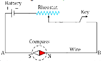
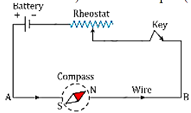
In Fig , AB is a wire lying in the north- south direction and connected to a battery through a rheostat and a tapping key. A compass needle is placed just below the wire. It is observed that
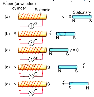
(1)When the key is open i.e., no current passes through the wire, the needle shows no deflection and it points in the N-S direction (i.e. along the earth's magnetic field). In this position, the needle is parallel to the wire as shown in Fig. (a).


(a) When a key is open ,the needle showe no deflection and it puint in the N S direction.
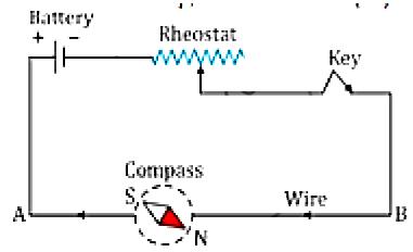
(2)When the key is pressed, a current passes in the wire in the direction from A to B (i.e. From south to north) and the north pole(N) of the needle deflects towards the west [Fig. (b)].


(b) When the kei is ,pressed, the nother pole (N)of the needle deflects towards the west.
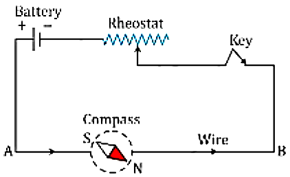
(3) When the direction of current in the wire is reversed by reversing the connections at the
terminals of the battery, North Pole (N) of the needle deflects towards the east [Fig. (c)].


(c) When the direction of current in the wire is reversed, the north pole (N) of the needle deflects towards the east.


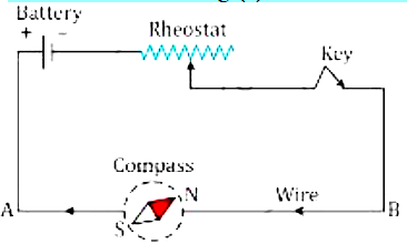
(d) If the compass needle is placed just above the wire, the north pole (N) deflects towards east when the direction of current in wire is frum A to B .
(4) If the compass needle is placed just above the wire, the North Pole (N) deflects towards
east when the direction of current in wire is from A to B [Fig. (d)], but the needle deflects
towards west as in fig (e), if the direction of current in wire is from B to A.


(a) If the compass needle is placed just above the wire the needle deflects towareds west it thye direction of current in wire is from B to A.
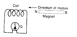
The above observations of the experiment suggest that a current carrying wire produces a
magnetic field around it.
View full question & answer
[5 Mark Question Answer] - Physics STD 10 Questions - Vidyadip