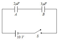
Two capacitors A and B are connected in series with a battery as shown in the figure. When the switch S is closed and the two capacitors get charged fully, then
A
The potential difference across the plates of A is 4V and across the plates of B is 6V
✓
The potential difference across the plates of A is 6V and across the plates of B is 4V
C
The ratio of electrical energies stored in A and B is 2 : 3
D
The ratio of charges on A and B is 3 : 2
Answer
Correct option: B.
The potential difference across the plates of A is 6V and across the plates of B is 4V
(b) The potential difference across the plates of A is 6V and across the plates of B is 4V
Two capacitors of capacitance 2 μF and 3μF are joined in series. Outer plate first capacitor is at 1000 volt and outer plate of second capacitor is earthed (grounded). Now the potential on inner plate of each capacitor will be
A series combination of three capacitors of capacities 1μF, 2 μF and 8 μF is connected to a battery of e.m.f. 13 volt. The potential difference across the plates of 2 μF capacitor will be
A capacitor of capacity $C_1$ is charged upto V volt and then connected to an uncharged capacitor of capacity $C_2$. Then final potential difference across each will be
Two capacitors of capacitances 3 μF and 6 μF are charged to a potential of 12 V each. They are now connected to each other, with the positive plate of each joined to the negative plate of the other. The potential difference across each will be
Three capacitors of 2μF, 3μF and 6μF are joined in series and the combination is charged by means of a 24 volt battery. The potential difference between the plates of the 6 μF capacitor is
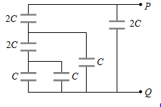
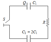
Two capacitors $\mathrm{C}_1$ and $\mathrm{C}_2=2 \mathrm{C}_1$ are connected in a circuit with a switch between them as shown in the figure. Initially the switch is open and $\mathrm{C}_1$ holds charge Q. The switch is closed. At steady state, the charge on each capacitor will be
A parallel plate capacitor has capacitance C. If it is equally filled with parallel layers of materials of dielectric constants $\mathrm{K}_1$ and $\mathrm{K}_2$ its capacity becomes $C_1$. The ratio of $C_1$ to $C$ is
A 20F capacitor is charged to 5V and isolated. It is then connected in parallel with an uncharged 30F capacitor. The decrease in the energy of the system will be
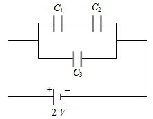
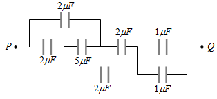
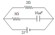
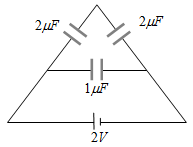
Two capacitors ${C}_1=2 \mu{F}$ and ${C}_6=2 \mu{F}$ in series, are connected in parallel to a third capacitor${C}_3=4 \mu{F}$. This arrangement is then connected to a battery of e.m.f. = 2V, as shown in the figure. How much energy is lost by the battery in charging the capacitors
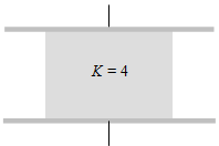
Consider a parallel plate capacitor of 10 μF (micro-farad) with air filled in the gap between the plates. Now one half of the space between the plates is filled with a dielectric of dielectric constant 4, as shown in the figure. The capacity of the capacitor changes to
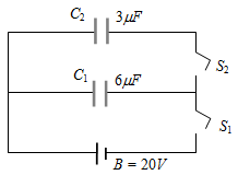
In the circuit shown here $C_1=6\mu F,C_2=3\mu F$ and battery B = 20V. The switch $S_1$ is first closed. It is then opened and afterwards $S_2$ is closed. What is the charge finally on $C_2$
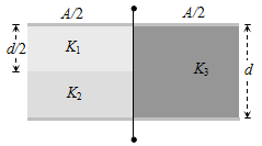
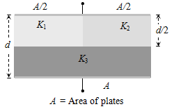
A parallel plate capacitor of area A, plate separation d and capacitance C is filled with three different dielectric materials having dielectric constants $k_1,k_2$ and $k_3$ as shown. If a single dielectric material is to be used to have the same capacitance C in this capacitor, then its dielectric constant k is given by
Ten capacitor are joined in parallel and charged with a battery up to a potential V. They are then disconnected from battery and joined again in series then the potential of this combination will be
A potential difference of 300 volts is applied to a combination of 2.0mF and 8.0mF capacitors connected in series. The charge on the 2.0mF capacitor is
The equivalent capacitance of three capacitors of capacitance $C_1,C_2$ and $C_3$ are connected in parallel is 12 units and product $C_1 \cdot C_2 \cdot C_3=48$. When the capacitors $C_1$ and $C_2$ are connected in parallel, the equivalent capacitance is 6 units. Then the capacitance are
A capacitor of 20 μF is charged to 500 volts and connected in parallel with another capacitor of 10 μF and charged to 200 volts. The common potential is
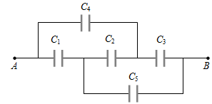
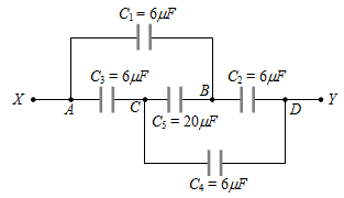
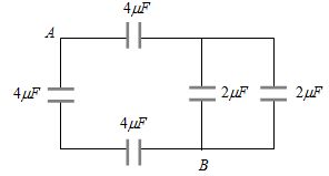
In the given figure the capacitors $C_1,C_3,C_4,C_5$ have a capacitance 4mF each if the capacitor $C_2$ has a capacitance 10mF, then effective capacitance between A and B will be
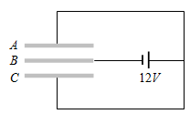
Three plates A, B, C each of area $50\ cm^2$ have separation 3mm between A and B and 3mm between B and C The energy stored when the plates are fully charged is
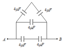
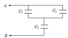
The combination of capacitors with $C_1=3\mu F, C_2=4\mu F$ and $C_3=2\mu F$ is charged by connecting AB to a battery. Consider the following statements
I. Energy stored in $C_1$ = Energy stored in $C_2$ + Energy stored in $C_3$
II. Charge on $C_1$ = Charge on $C_2$ + Charge on $C_3$
III. Potential drop across $C_1$ = Potential drop across $C_2$ = Potential drop across $C_3$
Which of these is/are correct
A 10 μF capacitor is charged to a potential difference of 50 V and is connected to another uncharged capacitor in parallel. Now the common potential difference becomes 20 volt. The capacitance of second capacitor is
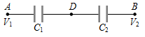
Two condensers $C_1$ and $C_2$ in a circuit are joined as shown in figure. The potential of point A is $V_1$ and that of B is$V_1$. The potential of point D will be
A 10 $\mu \mathrm{F}$ capacitor and a 20 $\mu \mathrm{F}$ capacitor are connected in series across a 200 V supply line. The charged capacitors are then disconnected from the line and reconnected with their positive plates together and negative plates together and no external voltage is applied. What is the potential difference across each capacitor
Choose the incorrect statement from the following: When two identical capacitors are charged individually to different potentials and connected parallel to each other after disconnecting them from the source
A
Net charge equals the sum of initial charges
B
The net energy stored in the two capacitors is less than the sum of the initial individual energies
C
The net potential difference across them is different from the sum of the individual initial potential difference
✓
The net potential difference across them equals the sum of the individual initial potential differences
Answer
Correct option: D.
The net potential difference across them equals the sum of the individual initial potential differences
The net potential difference across them equals the sum of the individual initial potential differences
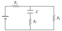
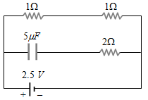
A capacitor of capacitance 5$\mu F$ is connected as shown in the figure. The internal resistance of the cell is 0.5 Ω. The amount of charge on the capacitor plate is


 (a) (b) (c) (d)