Question 13 Marks
Obtain the formula of electric current for an AC circuit having only capacitor.
Answer
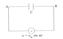
→As shown in the fig., an AC source is connected to a capacitor.
→Voltage of the AC source,
$v=v_m \sin \omega t$
→A capacitor connected to an AC source, limits or regulates the current, but does not completely prevent the flow of charge.
→The capacitor is alternatively charged and discharged as the current reverses each half cycle.
→Let $q$ be the charge on the capacitor at any time $t$.
→The instantaneous voltage $v$ across the capacitor is,
$\begin{array}{ll}
& v=\frac{q}{ C } \\
\therefore & v_m \sin \omega t=\frac{ q }{ C } \\
\therefore & q=v_m \cdot C \sin \omega t
\end{array}$
→To find the current, we use the relation,
$\begin{aligned}
& i=\frac{d q}{d t} \\
\therefore \quad & \frac{d q}{d t}=v_m C \frac{d}{d t}(\sin \omega t) \\
\therefore \quad & i=v_m \omega C \cos \omega t \\
\therefore \quad i= & v_m \omega C \sin \left(\omega t+\frac{\pi}{2}\right) \\
\therefore \quad i= & \frac{v_m}{\frac{1}{\omega C}} \sin \left(\omega t+\frac{\pi}{2}\right) \\
\therefore \quad & i=i_m \sin \left(\omega t+\frac{\pi}{2}\right)
\end{aligned}$
Where $i_m=\frac{v_m}{\frac{1}{\omega C}}$ (Amplitude of current)
→This equation is similar to the equation
$i_m=\frac{v_m}{R}$ for a purely resistive circuit.
→Thus, the term $\frac{1}{\omega C }$ is similar (or analogus) to resistor in D.C. circuit.
→It is called capacitive reactance and is denoted by $X _{ C }$.
$\therefore \quad X _{ C }=\frac{1}{\omega C } \text { (Unit : ohm }(\Omega) \text { ) }$
→Therefore, the amplitude of electirc current
$i_m=\frac{v_m}{ X _{ C }}$
→From eq. (1) and (2), it can be said that current is $\frac{\pi}{2} rad$ ahead of voltage in phase.
View full question & answer→→As shown in the fig., an AC source is connected to a capacitor.
→Voltage of the AC source,
$v=v_m \sin \omega t$
→A capacitor connected to an AC source, limits or regulates the current, but does not completely prevent the flow of charge.
→The capacitor is alternatively charged and discharged as the current reverses each half cycle.
→Let $q$ be the charge on the capacitor at any time $t$.
→The instantaneous voltage $v$ across the capacitor is,
$\begin{array}{ll}
& v=\frac{q}{ C } \\
\therefore & v_m \sin \omega t=\frac{ q }{ C } \\
\therefore & q=v_m \cdot C \sin \omega t
\end{array}$
→To find the current, we use the relation,
$\begin{aligned}
& i=\frac{d q}{d t} \\
\therefore \quad & \frac{d q}{d t}=v_m C \frac{d}{d t}(\sin \omega t) \\
\therefore \quad & i=v_m \omega C \cos \omega t \\
\therefore \quad i= & v_m \omega C \sin \left(\omega t+\frac{\pi}{2}\right) \\
\therefore \quad i= & \frac{v_m}{\frac{1}{\omega C}} \sin \left(\omega t+\frac{\pi}{2}\right) \\
\therefore \quad & i=i_m \sin \left(\omega t+\frac{\pi}{2}\right)
\end{aligned}$
Where $i_m=\frac{v_m}{\frac{1}{\omega C}}$ (Amplitude of current)
→This equation is similar to the equation
$i_m=\frac{v_m}{R}$ for a purely resistive circuit.
→Thus, the term $\frac{1}{\omega C }$ is similar (or analogus) to resistor in D.C. circuit.
→It is called capacitive reactance and is denoted by $X _{ C }$.
$\therefore \quad X _{ C }=\frac{1}{\omega C } \text { (Unit : ohm }(\Omega) \text { ) }$
→Therefore, the amplitude of electirc current
$i_m=\frac{v_m}{ X _{ C }}$
→From eq. (1) and (2), it can be said that current is $\frac{\pi}{2} rad$ ahead of voltage in phase.