Questions

5 Marks Questions

Take a timed test

6 questions · self-marked practice — reveal the answer and mark yourself.

Question 15 Marks
$a.$ Use Huygen's geometrical construction to show how a plane wavefront at $t = 0$ propagates and produces a wavefront at a later time.
$b.$ Verify, using Huygen's principle, Snell's law of refraction of a plane wave propagating from a denser to a rarer medium.
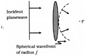
$c.$ Illustrate with the help of diagrams the action of
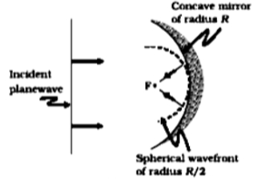
$i.$ convex lens and
$ii.$ concave mirror, on a plane wavefront incident on it.
Answer
$a.$ The surface of constant phase is known as a wavefront.
Image

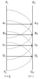
The Geometrical construction of wavefront:
To determine the wavefront at $t =\tau$ draw spheres of radius $v \tau$ from each point on $F _1 F_2$ and draw a common tangent to these spheres to obtain the new position of the wavefront.
Image

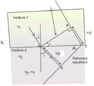
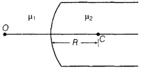
The ratio of the speed of light in vaccum to the speed of light in the medium is termed as refractive index of medium. Let us consider the medium $I,$ which is optically denser than medium $2.$
Let the speed of light be $v_1$ in medium $I$ and $v_2$ in medium $II.$
Always, note that $v_2>v_1$
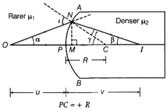
A plane wave $AB$ propagates and hits the interface at an angle $i.$ and can be the time taken be the wavefront to travel the distance $BC.$
Now, we want to draw the refracted wavefront.
We can draw a sphere of radius $v _2$ with $A$ as centre. Let the surface tangent to the sphere passing through point $C$ , as the refracted wavefront.
Now,
Let the surface be tangent to the sphere at $E$.
In $\triangle ABC$
$\sin i =\frac{v_1 t}{A C}$ and,
In $\triangle AEC \iota$
$\sin r =\frac{v_2 t}{A C}$
On dividing both the equations, we finally have,
$\frac{\sin i}{\sin r}=\frac{v_1}{v_2}=\frac{\frac{c}{v_2}}{\frac{c}{v_1}}$
Hence, $\frac{\sin i}{\sin r}=\frac{n_2}{n_1}$
This is the verified Snell's law.
Image

Image
View full question & answer
Question 25 Marks
Figure shows a convex spherical surface with centre of curvature $C$ separating the two media of refractive indices $\mu_1$ and $\mu_2$. Draw a ray diagram showing the formation of the image of a point object $O$ lying on the principal axis. Derive the relationship between the object and image distance in terms of refractive indices of the media and the radius of curvature $R$ of the surface.
Image
Answer
The ray diagram is shown in the figure.
Image
Let $, NM = h$
The convex spherical refracting surface forms the image of object $O$ at $I$. The radius of curvature is $R$
Here  $P I=+v$ and $P O=-u$
In $ \triangle N C O, i=\gamma+\alpha \ldots \text { (i) }$
In $\triangle N C I, \gamma=r+\beta$
$\Rightarrow r=\gamma-\beta \ldots \text { (ii) }$
For small angles $\alpha, \beta$ and $\gamma$ and assuming $M$ is very close to $P,$ we have
$\alpha \approx \tan \alpha=\frac{M N}{M O}=\frac{M N}{P O}=\frac{+h}{-u}$
$\beta \approx \tan \beta=\frac{M N}{M I}=\frac{M N}{P I}=\frac{h}{v}$
$\gamma \approx \tan \gamma=\frac{M N}{M C}=\frac{M N}{P C}=\frac{h}{+R}$
By Snell's law,
$\frac{\mu_2}{\mu_1}=\mu=\frac{\sin i}{\sin r}$
For small $i$ and $r,$
$\frac{\mu_2}{\mu_1}=\frac{i}{r}$ or $ r \mu_2=i \mu_1$
$\mu_2(\gamma-\beta)=(\alpha+\gamma) \mu_1 \ [$From Eqs. $(i)$ and $(ii)]$
$\left(\mu_2-\mu_1\right) \gamma=\mu_1 \alpha+\mu_2 \beta$
$\left(\mu_2-\mu_1\right)\left(\frac{h}{R}\right)$
$=\mu_1\left(\frac{h}{-u}\right)+\mu_2\left(\frac{h}{v}\right)$
$\Rightarrow \frac{\mu_2}{v}-\frac{\mu_1}{u}$
$=\frac{\mu_2-\mu_1}{R}$
This is the required relation.
View full question & answer
Question 35 Marks
$i$. What do you understand by the sharpness of resonance in a series $L-C-R$ circuit? Derive an expression for $Q$ factor of the circuit.
$ii$. Three electrical circuits having $AC$ sources of variable frequency are shown in the figures.
Initially, the current flowing in each of these is same. If the frequency of the applied $AC$ source is increased, how will the current flowing in these circuits be affected? Give the reason for your answer.
Image ​​​​​​​
Answer
$i$. The sharpness of resonance in series $L-C-R$ circuit refers how quick fall of alternating current in circuit takes place when the frequency of alternating voltage shifts away from the resonant frequency.
It is measured by the quality factor $(Q-$ factor$)$ of circuit.
Image
The $Q -$ factor of the series resonant circuit is defined as the ratio of the voltage developed across the capacitance or inductance at resonance to the impressed voltage which is the voltage applied.
$\text { i.e., quality factor }( Q )=\frac{\text { voltageacross } L \text { or } C}{\text { applied voltage }}$
$Q =\frac{\left(\omega_{ r } L\right) I}{R I}$
$[\because $ applied voltage $=$ voltage across $R ]$
$\text { or } Q =\frac{\omega_r L}{R} \text { or } Q =\frac{\left(1 / \omega_r C\right) I}{R I}=\frac{1}{R C \omega_r}$
$\therefore Q =\frac{L}{R C \cdot \frac{1}{\sqrt{L C}}} \text { [using } \omega_r=\frac{1}{\sqrt{L C}}$
Thus $, Q =\frac{1}{R} \sqrt{\frac{L}{C}}$
This is required expression.
$ii$. Let initially $I _{ r }$ current is flowing in all the three circuits. If the frequency of applied $AC$ source is increased then, the change in current will occur in the following manner:
Circuit containing resistance $R$ only:
Image
where, $f _{ i }=$ initial frequency of $AC$ source.
There is no effect on current with the increase in frequency.
$AC$ circuit containing inductance only:
Image
With the increase of frequency of $AC$ source, inductive reactance increase as
$I=\frac{V_\text{ rms }}{X_L}=\frac{V_\text{ mms }}{2 \pi f L}$
For given circuit,
$I \propto \frac{1}{f}$
Current decreases with the increase of frequency.
$AC$ circuits containing capacitor only:
Image

$ X _{ C }=\frac{1}{\omega C}=\frac{1}{2 \pi f C}$
$\text { Current, } I =\frac{V_\text{ mms }}{X_{ C }}=\frac{V_\text{ rms }}{\left(\frac{1}{2 \pi f C}\right)}$
$I =2 \pi f C V_\text{ rms }$
For given circuit, $I \propto f$
Current increases with the increase of frequency.
View full question & answer
Question 45 Marks
$a$. Show that an ideal inductor does not dissipate power in an ac circuit.
$b$. The variation of inductive reactance $\left( X _{ L }\right)$ of an inductor with the frequency $(f)$ of the ac source of $100 V$ and variable frequency is shown in the fig.
Image

$i$. Calculate the self-inductance of the inductor.
$ii.$ When this inductor is used in series with a capacitor of unknown value and a resistor of $10 \Omega$ at $300 s^{-1},$ maximum power dissipation occurs in the circuit. Calculate the capacitance of the capacitor.
Answer
$a$. Power dissipation $= P = V _{\text {rms }} I _{\text {rms }} \cos \phi$
$\cos \phi=\frac{R}{Z}$
For ideal inductor $R =0$
$\therefore \cos \phi=0$
$\therefore P = V _{\text {rms }} I _{ rms } \cos \phi=0$
Thus, ideal inductor does not dissipate power in an $ac$ circuit.
$b. i.$ Inductive reactance $=X_L=2 \pi fL$
$\therefore L =\frac{X_L}{2 \pi f}$
From graph, at $f = 100 Hz$
$X _{ L }=20 \Omega$
$\therefore L =\frac{X_L}{2 \pi f}=\frac{20}{2 \pi \times 100}$
$=0.032 H =32 mH $
$ii$. Power dissipation is maximum when
$2 \pi fL =\frac{1}{2 \pi f C}$
$f =300 s^{-1}$
$L=0.032 H$
$2 \pi fL =\frac{1}{2 \pi f C}$
Or $, 2 \pi \times 300 \times 0.032$
$=\frac{1}{2 \pi \times 300 \times C}$
$\therefore C =8.8 \times 10^{-6} F$
$=8.8 \mu F$
View full question & answer
Question 55 Marks
$i. A$ Why does the electric field inside a dielectric slab decrease when kept in an external electric field?
$B$. Derive an expression for the capacitance of a parallel plate capacitor filled with a medium of dielectric constant K.
$ii$. A charge $q =2 \mu C$ is placed at the centre of a sphere of radius $20 \ cm$ . What is the amount of work done in moving $4 \mu C$ from one point to another point on its surface?
$iii.$ Write a relation for polarisation $\overrightarrow{ P }$ of a dielectric material in the presence of an external electric field.
Answer
$i. A. A$ dielectric material gets polarized when it is placed in an external electric field.
The field produced due to the polarization of material reduces the effect of external electric field.
Hence, the electric field inside a dielectric decreases.
$B$. Electric field in vacuum between the plates $= E 0=\frac{\sigma}{\varepsilon_0}$
Electric field in dielectric between the plates, $E =\frac{E_0}{K}$
Potential difference between the capacitor plates
$V=E t+E_0(d-t)$
where $'t\ '$ is the thickness of dielectric slab.
$ V =\frac{E_0}{K} t + E _0(d- t )$
$V =\frac{\sigma}{\varepsilon_o}\left[\frac{t}{K}+( d - t )\right]$
$V =\frac{\sigma}{\varepsilon_o}\left[\frac{t+K(d-t)}{K}\right]$
$\text { As } C =\frac{Q}{V}$
$\Rightarrow C =\frac{\varepsilon_0 A K}{t+K(d-t)}$
$ii.$ The surface of the sphere is equipotential.
So, the work done in moving the charge from one point to the other is zero.
$ W = q \Delta V (\because \Delta V =0)$
$=0$
$iii. P =\chi E$
View full question & answer
Question 65 Marks
In Fig. the energy stored in $C _4$ is 27 J . Calculate the total energy stored in the system.
Image
Answer
Energy stored in $C _4$ is
$U_4=\frac{1}{2} C_4 V^2=27 J$
or $ \frac{1}{2} \times 6 \times 10^{-6} \times V ^2=27$
or $V^2=\frac{27 \times 2}{6 \times 10^{-6}}$
$=9 \times 10^6$
Energy stored in $C _3$,
$U _3=\frac{1}{2} \times 3 \times 10^{-6} \times 9 \times 10^6=13.5 J$
Energy stored in $C _2, C _3$ and $C _4$
$=U_2+U_3+U_4$
$=9+13.5+27=49.5 J$
Equivalent capacitance of $C_2, C_3$ and $C_4$ connected in parallel
$=2+3+5=11 \mu F$
$\therefore \frac{q^2}{2 \times 11 \times 10^{-6}}=49.5 J \quad\left[u=\frac{q^2}{2 C}\right]$
Energy stored in $C _1$
$U_1=\frac{q^2}{2 C_1}$
$=\frac{49.5 \times 2 \times 11 \times 10^{-6}}{2 \times 1 \times 10^{-6}}$
$=544.5 J$
Total energy stored in the arrangement
$= 544.5 + 49.5 = 594.0 J$
View full question & answer