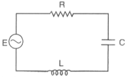
Question 15 Marks
$a.$ Using the ray diagram for a system of two lenses of focal lengths $f_1$ and $f_2$ in contact with each other, show that the two lens system can be regarded as equivalent to a single lens of focal length $f$, where
$\frac{1}{ f }=\frac{1}{ f _1}+\frac{1}{ f _2}$
Also write the relation for the equivalent power of the lens combination.
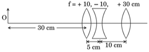
$b.$ Determine the position of the image formed by the lens combination given in the figure.
$\frac{1}{ f }=\frac{1}{ f _1}+\frac{1}{ f _2}$
Also write the relation for the equivalent power of the lens combination.
$b.$ Determine the position of the image formed by the lens combination given in the figure.
Answer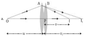
For less $A$
$\frac{1}{f_1}=\frac{1}{v_1}-\frac{1}{u}$ eg. $(I)$
For less $B$
$\frac{1}{f_2}=\frac{1}{v}-\frac{1}{v_1}$ eg.$(II)$
Adding eqn. $(i)$ eqn. $(ii)$
$\frac{1}{f_1}+\frac{1}{f_2}=\frac{1}{v_1}-\frac{1}{ u }+\frac{1}{ v }-\frac{1}{ v _1}$
$\frac{1}{f_1}+\frac{1}{f_2}=\frac{1}{ v }-\frac{1}{ u }$
$\frac{1}{f_1}+\frac{1}{f_2}=\frac{1}{F}$
$\therefore$ equivalent power
$P = P _2+ P _2$
b. Image formed by lense of $f = +10 \ cm$
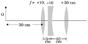
$\frac{1}{v_1}-\frac{1}{u_1}=\frac{1}{f_1}$
$\frac{1}{v_1}-\frac{1}{30}=\frac{1}{10}$
$\therefore v_1=15 \ cm$
This image formed by the lens act as object from concave lens
$\therefore u _2=15-5=10 \ cm$
$\frac{1}{f_2}+\frac{1}{v_2}=\frac{1}{v_2}$
$\frac{1}{-10}=\frac{1}{v}-\frac{1}{10}$
$v=\infty$
Therefore virtual image forms at right of concave lens at $v=\infty$ and act as convex lens. ( $f=+30 \ cm$ )
$\therefore u _2=15-5=10 \ cm$
$\frac{1}{v_3}=\frac{1}{4}-\frac{1}{f_3}$
$\frac{1}{v_3}=\frac{1}{\infty}=\frac{1}{30}$
$v_3=30 \ cm$
View full question & answer→For less $A$
$\frac{1}{f_1}=\frac{1}{v_1}-\frac{1}{u}$ eg. $(I)$
For less $B$
$\frac{1}{f_2}=\frac{1}{v}-\frac{1}{v_1}$ eg.$(II)$
Adding eqn. $(i)$ eqn. $(ii)$
$\frac{1}{f_1}+\frac{1}{f_2}=\frac{1}{v_1}-\frac{1}{ u }+\frac{1}{ v }-\frac{1}{ v _1}$
$\frac{1}{f_1}+\frac{1}{f_2}=\frac{1}{ v }-\frac{1}{ u }$
$\frac{1}{f_1}+\frac{1}{f_2}=\frac{1}{F}$
$\therefore$ equivalent power
$P = P _2+ P _2$
b. Image formed by lense of $f = +10 \ cm$
$\frac{1}{v_1}-\frac{1}{u_1}=\frac{1}{f_1}$
$\frac{1}{v_1}-\frac{1}{30}=\frac{1}{10}$
$\therefore v_1=15 \ cm$
This image formed by the lens act as object from concave lens
$\therefore u _2=15-5=10 \ cm$
$\frac{1}{f_2}+\frac{1}{v_2}=\frac{1}{v_2}$
$\frac{1}{-10}=\frac{1}{v}-\frac{1}{10}$
$v=\infty$
Therefore virtual image forms at right of concave lens at $v=\infty$ and act as convex lens. ( $f=+30 \ cm$ )
$\therefore u _2=15-5=10 \ cm$
$\frac{1}{v_3}=\frac{1}{4}-\frac{1}{f_3}$
$\frac{1}{v_3}=\frac{1}{\infty}=\frac{1}{30}$
$v_3=30 \ cm$