Question 15 Marks
$a.$ Derive the expression for the current flowing in an ideal capacitor and its reactance when connected to an ac source of voltage $V = V _{ o } \sin \omega t$.
$b.$ Draw its phasor diagram.
$c.$ If resistance is added in series to capacitor what changes will occur in the current flowing in the circuit and phase angle between voltage and current.
$b.$ Draw its phasor diagram.
$c.$ If resistance is added in series to capacitor what changes will occur in the current flowing in the circuit and phase angle between voltage and current.
Answer
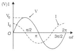
View full question & answer→$a.$ We have $V = V _{ o } \sin \omega t$.
Also, $v =\frac{q}{c} ; q =$ charge on capacitor
$v _0 \sin \omega t=\frac{q}{c}$
or, $q = cv _0 \sin \omega t$
$\therefore I =\frac{d q}{d t}=\frac{d}{d t}\left( CV _0 \sin \omega t\right)= cv _0 \sin \omega t \cdot \omega$
$\therefore I =\frac{ v _0}{\frac{1}{\omega t}} \sin \left(\omega t+\frac{\pi}{2}\right)$
Max. current, $I _{ o }=\frac{ v _o}{1} \times 1$ when $\sin \left(\omega t+\frac{\pi}{2}\right)=1$
Comparing with ohm's law: $I =\frac{V}{R}$ to equation $I _{ o }=\frac{ v _o}{\frac{1}{ uc }}$
We have, capacitive reactance, $x _{ C }=\frac{1}{\omega c}$
$b.$ Phasor diagram:

$c.$ A resistor is now connected with the capacitor in series:
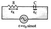
Peak voltage drop across $R$ is $i_0 R$
Peak voltage drop across $C$ is $i_0 X_C$.
Voltage a cross $R$ is in phase with the current.
Voltage across $C$ lags the current by $90^{\circ}$.
So, the voltage drops across $R$ and across $C$ are not in phase.
They are out of phase by $90^{\circ}$.
$\text { So, } \varepsilon_0=\sqrt{\left(i_0 R\right)^2+\left(i_0 X_C\right)^2}$
$\therefore i _0=\frac{V_0}{\sqrt{R^2+X_C^2}}$
The phase angle is
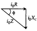
Phase Angle $=\phi=\tan ^{-1} \frac{X_C}{R}$
Also, $v =\frac{q}{c} ; q =$ charge on capacitor
$v _0 \sin \omega t=\frac{q}{c}$
or, $q = cv _0 \sin \omega t$
$\therefore I =\frac{d q}{d t}=\frac{d}{d t}\left( CV _0 \sin \omega t\right)= cv _0 \sin \omega t \cdot \omega$
$\therefore I =\frac{ v _0}{\frac{1}{\omega t}} \sin \left(\omega t+\frac{\pi}{2}\right)$
Max. current, $I _{ o }=\frac{ v _o}{1} \times 1$ when $\sin \left(\omega t+\frac{\pi}{2}\right)=1$
Comparing with ohm's law: $I =\frac{V}{R}$ to equation $I _{ o }=\frac{ v _o}{\frac{1}{ uc }}$
We have, capacitive reactance, $x _{ C }=\frac{1}{\omega c}$
$b.$ Phasor diagram:
$c.$ A resistor is now connected with the capacitor in series:
Peak voltage drop across $R$ is $i_0 R$
Peak voltage drop across $C$ is $i_0 X_C$.
Voltage a cross $R$ is in phase with the current.
Voltage across $C$ lags the current by $90^{\circ}$.
So, the voltage drops across $R$ and across $C$ are not in phase.
They are out of phase by $90^{\circ}$.
$\text { So, } \varepsilon_0=\sqrt{\left(i_0 R\right)^2+\left(i_0 X_C\right)^2}$
$\therefore i _0=\frac{V_0}{\sqrt{R^2+X_C^2}}$
The phase angle is
Phase Angle $=\phi=\tan ^{-1} \frac{X_C}{R}$