$3$ identical bulbs are connected in series and these together dissipate a power $P$. If now the bulbs are connected in parallel, then the power dissipated will be
Medium


Download our appand get started for free
Experience the future of education. Simply download our apps or reach out to us for more information. Let's shape the future of learning together!No signup needed.*
Similar Questions
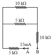
- 1A current of $15\,mA$ flows in the circuit as shown in figure. The value of potential difference between the points $A$ and $B$ will be $...\,V$View Solution
- 2A Copper $(Cu)$ rod of length $25\, {cm}$ and cross- sectional area $3\, {mm}^{2}$ is joined with a similar Aluminium $(Al)$ rod as shown in figure. Find the resistance of the combination between the ends $A$ and $B$ (in ${m} \Omega$)View Solution
(Take Resistivity of Copper $=1.7 \times 10^{-8}\, \Omega \,{m}$, Resistivity of Aluminium $=2.6 \times 10^{-8}\, \Omega \,{m}$ )

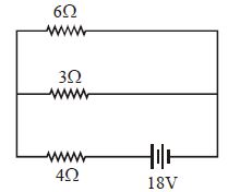
- 3The total power dissipated in watts in the circuit shown is ............. $W$View Solution
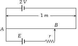
- 4In the given figure, battery $E $ is balanced on $55\, cm$ length of potentiometer wire but when a resistance of $10 \,\Omega$ is connected in parallel with the battery then it balances on $50\, cm$ length of the potentiometer wire then internal resistance $r$ of the battery is ............. $\Omega $View Solution
- 5If a $2\, kW$ boiler is used everyday for $1$ hour, then electrical energy consumed by boiler in thirty days is .......... $uint$View Solution
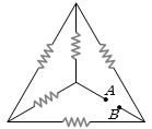
- 6In the network shown in the figure, each of the resistance is equal to $2\,\Omega $. The resistance between the points $A$ and $B$ is .............. $\Omega$View Solution
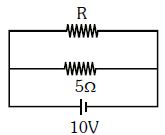
- 7The power dissipated in the circuit shown in the figure is $30\, Watts$. The value of $R$ is ............. $\Omega$View Solution
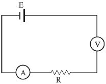
- 8Assertion : All electric devices shown in the circuit are ideal. The reading of each of ammeter $(a)$ and voltmeter $(V)$ is zero.View Solution
Reason : An ideal voltmeter draws almost no current due to very large resistance, and hence $(V)$ and $(a)$ will read zero.
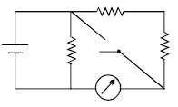
- 9In the circuit shown, the reading of the Ammeter is doubled after the switch is closed. Each resistor has a resistance $1\,\Omega $ and the ideal cell has an $e.m.f.$ $10\, V$. Then, the Ammeter has a coil resistance equal to ............... $\Omega$View Solution
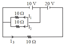
- 10In the given circuit the value of $\left|\frac{I_1+I_3}{I_2}\right|$ isView Solution