Gujarat BoardEnglish MediumSTD 12 SciencePhysicsSemiconductor Electronic: Material, Devices And Simple Circuits3 Marks
Question
✓
Answer
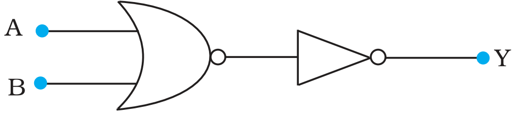
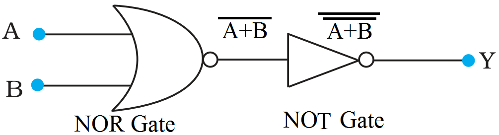
A and Bare the inputs and Y is the output of the given circuit. The left half of the given figure acts as the NOR Gate, while the right ha1f acts as the NOT Gate. This is shown in the following figure.
Hence, the output of the NOR Gate $=\overline{\text{A+B}}$
This will be the input for the NOT Gate. Its output wHI be ${\overline{\overline{A+B}}}=\text{A+B}$
$\therefore$ Y = A +B
Hence, this circuit functions as an OR Gate.
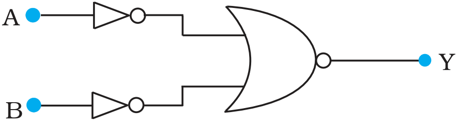
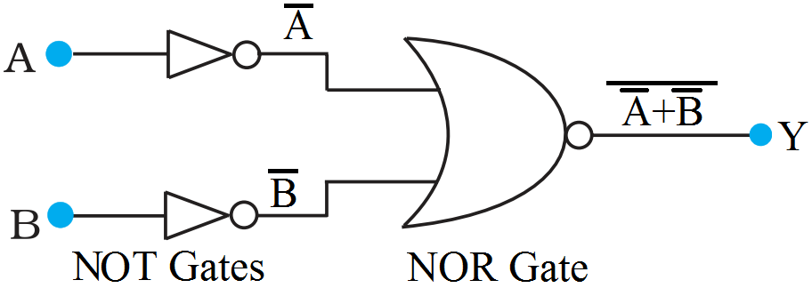
A and B are the inputs and Y is the output of the given circuit. It can be observed from the following figure that the Inputs of the right half NOR Gate are the outputs of the two NOT Gates.
Hence, the output of the given circuit can be written as:
$ \text{Y}={\overline{\overline{\text{A}}+{\overline{\text{B}}}}}={\overline{\overline{\text{A}}\cdot{\overline{\text{B}}}}}=\text{A}\cdot\text{B}$
Hence, this circuit functions as an AND Gate.
Need a full question paper?
Generate a complete, print-ready paper with questions like this in minutes — across 16+ boards, with answer keys.