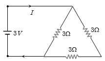
A $3\, volt$ battery with negligible internal resistance is connected in a circuit as shown in the figure. The current $I$, in the circuit will be ............. $A$
AIEEE 2003, Easy
Download our app for free and get started
$R = \frac{{(3 + 3) \times 3}}{{(3 + 3) + 3}} = 2\,\Omega $ $ \Rightarrow $ $i = \frac{3}{2} = 1.5\,A$.

Download our appand get started for free
Experience the future of education. Simply download our apps or reach out to us for more information. Let's shape the future of learning together!No signup needed.*
Similar Questions
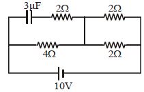
- 1Find charge stored on the capacitor in steady state condition .............. $\mu C$View Solution
- 2View SolutionWhich among the following is true
- 3View SolutionPotential gradient is defined as
- 4The resistance of a wire is $R$. If the length of the wire is doubled by stretching, then the new resistance will beView Solution
- 5A $10\, m$ long wire of $20\,\Omega$ resistance is connected with a battery of $3\, volt$ $e.m.f.$ (negligible internal resistance) and a $10 \,\Omega$ resistance is joined to it is series. Potential gradient along wire in volt per meter isView Solution
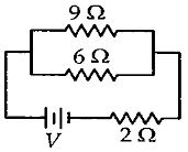
- 6If power dissipated in the $9 \,\Omega$ resistor in the circuit shown is $36\,W$, the potential difference across the $2 \,\Omega$ resistor is .......... $V$View Solution
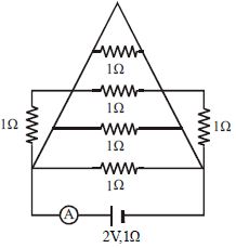
- 7In the circuit shown in Figure the ammeter reads a current ............. $A$View Solution
- 8View SolutionThe material of wire of potentiometer is
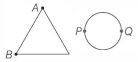
- 9A uniform metallic wire of length $L$ is mounted in two configurations. In configuration $1$ (triangle), it is an equilateral triangle and a voltage $V$ is applied to corners $A$ and $B$. In configuration $2$ (circle), it is bent in the form of a circle and the potential $V$ is applied at diametrically opposite points $P$ and $Q$. The ratio of the power dissipated in configuration $1$ to configuration $2$ isView Solution
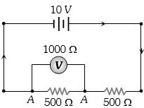
- 10What is the reading of voltmeter in the following figure .............. $V$View Solution