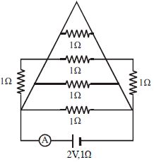
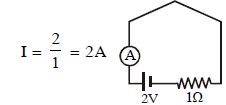
In the circuit shown in Figure the ammeter reads a current ............. $A$
Medium


Download our appand get started for free
Experience the future of education. Simply download our apps or reach out to us for more information. Let's shape the future of learning together!No signup needed.*
Similar Questions
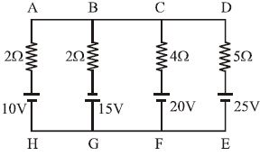
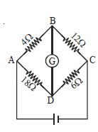
- 1In the given network current through branch $BG$ is almost equal to ............ $A$View Solution
- 2The resistance of a wire of iron is $10\, ohms$ and temp. coefficient of resistivity is $5 \times {10^{ - 3}}\,^oC$. At $20\,^oC$ it carries $30$ milliamperes of current. Keeping constant potential difference between its ends, the temperature of the wire is raised to $120\,^oC$. The current in milliamperes that flows in the wire isView Solution
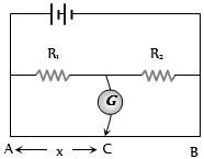
- 3In the shown arrangement of the experiment of the meter bridge if $AC$ corresponding to null deflection of galvanometer is $x$, what would be its value if the radius of the wire $AB$ is doubledView Solution
- 4View SolutionIn the following diagram the wheat stone bridge is balanced when we interchange the resistances of
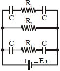
- 5In the circuit diagram of figure, $E = 5\, volt, r = 1\, \Omega ,$$ R_2 = 4\, \Omega , R_1 = R_3 = 1 \Omega$ and $C = 3\, μF.$ Then the magnitude of the charge on each capacitor plate is......$\mu C$View Solution
- 6View SolutionA piece of wire is cut into four equal parts and the pieces are bundled together side by side to form a thicker wire. Compared with that of the original wire, the resistance of the bundle is ..........
- 7A resistor ${R_1}$ dissipates the power $P$ when connected to a certain generator. If the resistor ${R_2}$ is put in series with ${R_1}$, the power dissipated by ${R_1}$View Solution
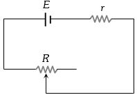
- 8A battery of $e.m.f.$ $E$ and internal resistance $r$ is connected to a variable resistor $R$ as shown here. Which one of the following is trueView Solution
- 9View SolutionFor which of the following the resistance decreases on increasing the temperature
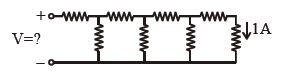
- 10Each element in the finite chain of resistors shown in the figure is $\,1\,\Omega $ . A current of $1\, A$ flows through the final element. Then what is the potential difference $V$ across input terminals of the chain .................. $\mathrm{volt}$View Solution