A galvanometer has resistance of $7\,\Omega $ and gives a full scale deflection for a current of $1.0\, A$. How will you convert it into a voltmeter of range $10\, V$
Medium
Download our app for free and get started
(a) By connecting a series resistance
$R = \frac{V}{{{i_g}}} - G = \frac{{10}}{1} - 7 = 3\,\Omega $
$R = \frac{V}{{{i_g}}} - G = \frac{{10}}{1} - 7 = 3\,\Omega $

Download our appand get started for free
Experience the future of education. Simply download our apps or reach out to us for more information. Let's shape the future of learning together!No signup needed.*
Similar Questions
- 1A coil having $N$ $turns$ is wound tightly in the form of a spiral with inner and outer radii $a$ and $b$ respectively. When a current $I$ passes through the coil, the magnetic field at the centre isView Solution
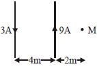
- 2Magnetic field at point $'M'$ of given current distributionView Solution
- 3The magnetic field on the axis of a circular loop of radius $100\,cm$ carrying current $I=\sqrt{2}\,A$, at point $1\,m$ away from the centre of the loop is given byView Solution
- 4A proton of mass $m$ and charge $+e$ is moving in a circular orbit in a magnetic field with energy $1\, MeV$. What should be the energy of $\alpha - $particle (mass = $4m$ and charge = $+ 2e),$ so that it can revolve in the path of same radius.......$MeV$View Solution
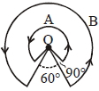
- 5A wire $A$, bent in the shape of an arc of a circle, carrying a current of $2\, A$ and having radius $2\, cm$ and another wire $B ,$ also bent in the shape of arc of a circle, carrying a current of $3\, A$ and having radius of $4\, cm ,$ are placed as shown in the figure. The ratio of the magnetic fields due to the wires $A$ and $B$ at the common centre $O$ isView Solution
- 6Two wires each carrying a steady current $I$ are shown in four configurations in Column $I$. Some of the resulting effects are described in Column $II$. Match the statements in Column $I$ with the statements in Column $II$ and indicate your answer by darkening appropriate bubbles in the $4 \times 4$ matrix given in the $ORS$.View Solution
Column $I$ Column $II$ $(A)$ Point $P$ is situated midway between the wires. $Image$ $(p)$ The magnetic fields $(B)$ at $P$ due to the currents in the wires are in the same direction. $(B)$ Point $P$ is situated at the mid-point of the line joining the centers of the circular wires, which have same radii. $Image$ $(q)$ The magnetic fields $(B)$ at $P$ due to the currents in the wires are in opposite directions. $(C)$ Point $P$ is situated at the mid-point of the line joining the centers of the circular wires, which have same radii. $Image$ $(r)$ There is no magnetic field at $P$. $(D)$ Point $P$ is situated at the common center of the wires. $Image$ $(s)$ The wires repel each other. 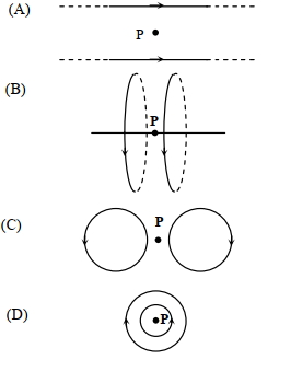
- 7A thin circular frame of radius $'a'$ is made of insulating material. A square loop is constructed with in it. If loop carrying current $I$ , then magnetic induction at geometrical centre $'O'$ will beView Solution

- 8View SolutionGauss is unit of which quantity
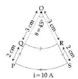
- 9A current loop, having two circular arcs joined by two radial lines is shown in the figure. It carries a current of $10\, A$. The magnetic field at point $O$ will be close toView Solution
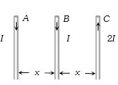
- 10$A, B$ and $C$ are parallel conductors of equal length carrying currents $I, I$ and $2I$ respectively. Distance between $A$ and $B$ is $x$. Distance between $B$ and $C$ is also $x$. ${F_1}$ is the force exerted by $B$ on $A$ and $F_2$ is the force exerted by $B$ on $A$ choose the correct answerView Solution