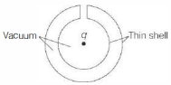
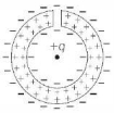
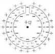
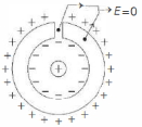
A positive charge $q$ is placed at the centre of a neutral hollow cylindrical conducting shell with its cross-section as shown in the figure below. Which one of the following figures correctly indicates the induced charge distribution on the conductor? (Ignore edge effects)
- A
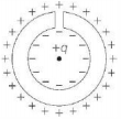
- B
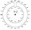
- C
- D
KVPY 2017, Advanced


Download our appand get started for free
Experience the future of education. Simply download our apps or reach out to us for more information. Let's shape the future of learning together!No signup needed.*
Similar Questions
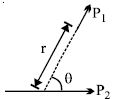
- 1View SolutionTwo short electric dipoles are placed as shown. The energy of electric interaction between these dipoles will be
- 2A proton is about $1840$ times heavier than an electron. When it is accelerated by a potential difference of $1\, kV$, its kinetic energy will be......$keV$View Solution
- 3A parallel plate capacitor has a uniform electric field $E$ in the space between the plates. If the distance between the plates is $d$ and area of each plate is $A,$ the energy stored in the capacitor isView Solution
- 4Two electrons are moving towards each other, each with a velocity of $10^6 \,m / s$. What will be closest distance of approach between them is ......... $m$View Solution
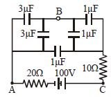
- 5In the figure below, what is the potential difference between the points $A$ and $B$ and between $B$ and $C$ respectively in steady stateView Solution
- 6The capacitance of a parallel plate capacitor is $5\, \mu F$ . When a glass slab of thickness equal to the separation between the plates is introduced between the plates, the potential difference reduces to $1/8$ of the original value. The dielectric constant of glass isView Solution
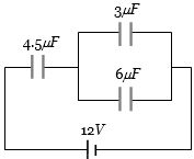
- 7In the circuit shown in the figure, the potential difference across the $4.5\,\mu F$ capacitor is.......$volts$View Solution
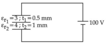
- 8A composite parallel plate capacitor is made up of two different dielectric materials with different thickness $\left(t_{1}\right.$ and $\left.t_{2}\right)$ as shown in figure. The two different dielectric material are separated by a conducting foil $F$. The voltage of the conducting foil is $.....V$View Solution
- 9The electrostatic force between the metal plates of an isolated parallel plate capacitor $C$ having a charge $Q$ and area $A,$ isView Solution
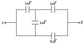
- 10Four capacitors are connected as shown in the figure. Their capacities are indicated in the figure. The effective capacitance between points $x$ and $y$ is (in $\mu F$)View Solution