A potential $V_0$ is applied across a uniform wire of resistance $R$. The power dissipation is $P_1$. The wire is then cut into two equal halves and a potential of $V _0$ is applied across the length of each half. The total power dissipation across two wires is $P_2$. The ratio $P_2: P_1$ is $\sqrt{x}: 1$. The value of $x$ is $.............$.
JEE MAIN 2023, Medium


Download our appand get started for free
Experience the future of education. Simply download our apps or reach out to us for more information. Let's shape the future of learning together!No signup needed.*
Similar Questions
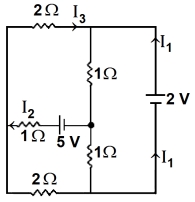
- 1In the following circuit, the magnitude of current $I _{ l }$, is $............A$.View Solution
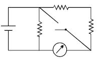
- 2In the circuit shown, the reading of the Ammeter is doubled after the switch is closed. Each resistor has a resistance $ = 1\,\Omega $ and the ideal cell has an $e.m.f. = 10\, V$. Then, the Ammeter has a coil resistance equal to ................ $\Omega$View Solution
- 3$n$ identical cells are joined in series with two cells $A$ and $B$ with reversed polarities. $emf$ of each cell is $E$ and internal resistance is $r$. Potential difference across cell $A$ and $B$ is : $(n > 4)$View Solution
- 4$n$ identical cells are joined in series with two cells $A$ and $B$ with reversed polarities. $emf$ of each cell is $E$ and internal resistance is $r$. Potential difference across cell $A$ and $B$ is : $(n > 4)$View Solution
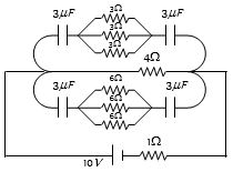
- 5In the following figure, the charge on each condenser in the steady state will be.....$\mu C$View Solution
- 6In the following $'I'$ refers to current and other symbols have their usual meaning, Choose the option that corresponds to the dimensions of electrical conductivityView Solution
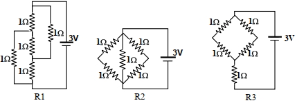
- 7Figure shows three resistor configurations $\mathrm{R} 1, \mathrm{R} 2$ and $\mathrm{R} 3$ connected to $3 \mathrm{~V}$ battery. If the power dissipated by the configuration $\mathrm{R} 1, \mathrm{R} 2$ and $\mathrm{R} 3$ is $\mathrm{P} 1, \mathrm{P} 2$ and $\mathrm{P} 3$, respectively, thenView Solution
Figure:
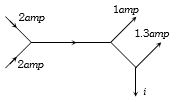
- 8The figure below shows currents in a part of electric circuit. The current $i$ is ............. $amp$View Solution
- 9A carbon resistor of $(47 \pm 4.7) \;k\Omega$ is to be marked with rings of different colours for its identification. The colour code sequence will bView Solution
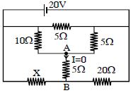
- 10In given circuit current through $AB$ is zero, then what will be the value of unknown resistance $'X'$ ............... $\Omega$View Solution