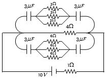
In the following figure, the charge on each condenser in the steady state will be.....$\mu C$
Medium


Download our appand get started for free
Experience the future of education. Simply download our apps or reach out to us for more information. Let's shape the future of learning together!No signup needed.*
Similar Questions
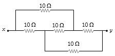
- 1The equivalent resistance between $x$ and $y$ in the circuit shown is ............. $\Omega$View Solution
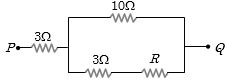
- 2In the circuit shown here, what is the value of the unknown resistor $R$ so that the total resistance of the circuit between points $P$ and $Q$ is also equal to $R$View Solution
- 3A current $I$ is passing through a wire having two sections $P$ and $Q$ of uniform diameters $d$ and $d/2$ respectively. If the mean drift velocity of electrons in sections $P$ and $Q$ is denoted by $v_P$ and $v_Q$ respectively, thenView Solution
- 4Two resistors are connected $(a)$ in series $(b)$ in parallel. The equivalent resistance in the two cases are $9$ $ohm$ and $2$ $ohm$ respectively. Then the resistances of the component resistors areView Solution
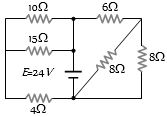
- 5Find the equivalent resistance across the terminals of source of $e.m.f$. $24\, V$ for the circuit shown in figure .............. $\Omega$View Solution
- 6A battery of $24$ cells, each of emf $1.5\, V$ and internal resistance $2\, \Omega$ is to be connected in order to send the maximum current through a $12 \,\Omega$ resistor. The correct arrangement of cells will beView Solution
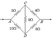
- 7Five resistors are connected as shown in the diagram. The equivalent resistance between $A$ and $B$ is .............. $ohm$View Solution
- 8The resistance of a wire is $R\; ohm$. If it is melted and stretched to $'n'$ times its original length, its new resistance will beView Solution
- 9Equivalent resistance between the adjacent corners of a regular $n$-sided polygon of uniform wire of resistance $R$ would be:View Solution
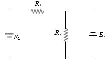
- 10Two resistances ${R_1}$ and ${R_2}$ are joined as shown in the figure to two batteries of $e.m.f.$ ${E_1}$ and ${E_2}$. If ${E_2}$ is short-circuited, the current through ${R_1}$ isView Solution