A radio can tune over the frequency range of a portion of MW broadcast band: (800kHz to 1200kHz). If its LC circuit has an effective inductance of 200μH, what must be the range of its variable capacitor?
[Hint: For tuning, the natural frequency i.e., the frequency of free oscillations of the LC circuit should be equal to the frequency of the radiowave.]
Exercise
Download our app for free and get started
The range of frequency (v) of a radio is 800kHz to 1200kHz.
Lower tuning frequency, $v_1 = 800kHz = 800 \times 10^3Hz$
Upper tuning frequency, $v_2 = 1200kHz = 1200 \times 10^3Hz$
Effective inductance of circuit $L = 200\mu H = 200 \times 10^{-6}H$
Capacitance of variable capacitor for $v_1$ is given as:
$\text{C}_1=\frac{1}{\omega_1^2\text{L}}$
Where,
$\omega_1=$ Angular frequency for capacitor $C_1$
$=2\pi\text{v}_1=2\pi\times800\times10^3\text{rad}\text{ s}^{-1}$
$\therefore\ \text{C}_1=\frac{1}{(2\pi\times800\times10^3)^2\times200\times10^{-6}}$
$= 1.9809 \times 10^{-10}F = 198.1\ pF$
Capacitance of variable capacitor for $v_2,$
$\text{C}_2=\frac{1}{\omega_2^2\text{L}}$
Where,
$\omega_2=$ Angular frequency for capacitor $C_2$
$=2\pi\text{v}_2=2\pi\times1200\times10^3\text{rad}\text{ s}^{-1}$
$\therefore\ \text{C}_2=\frac{1}{(2\pi\times1200\times10^3)^2\times200\times10^{-6}}$
= 88.04 pF
Hence, the range of the variable capacitor is from 88.04 pF to 198.1 pF

Download our appand get started for free
Experience the future of education. Simply download our apps or reach out to us for more information. Let's shape the future of learning together!No signup needed.*
Similar Questions
- 1View SolutionAn inductor 200 mH, capacitor 500 µF, resistor 10Ω are connected in series with a100 V, variable frequency a.c. source. Calculate the
- Frequency at which the power factor of the circuit is unity.
- Current amplitude at this frequency.
- Q-factor.
- 2View SolutionCalculate the following:
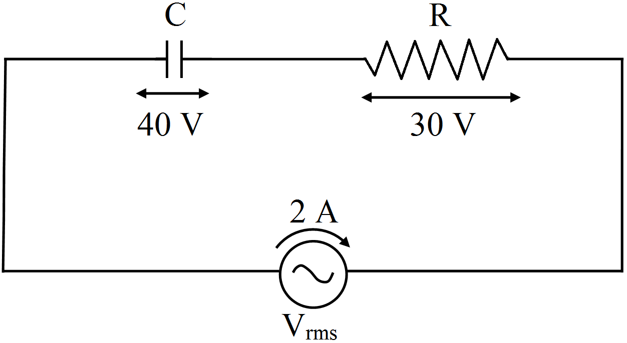
- Impedance of the given ac circuit.
- Wattless current of the given ac circuit.
- 3Draw a circuit diagram of a common emitter amplifier using n-p-n transistor. Derive an expression for the current gain $\beta_{ac}.$View Solution
- 4View Solution
- Derive the mathematical expression for law of radioactive decay for a sample of a radioactive nucleus.
- How is the mean life of a given radioactive nucleus related to the decay constant?
- 5View SolutionWhat is space wave propagation? State the factors which limit its range of propagation. Derive an expression for the maximum line of sight distance between two antennas for space wave propagation.
- 6View SolutionObtain the answers (a) to (b) in Exercise 7.13 if the circuit is connected to a high frequency supply (240V, 10kHz). Hence, explain the statement that at very high frequency, an inductor in a circuit nearly amounts to an open circuit. How does an inductor behave in a dc circuit after the steady state?
- 7View SolutionAn object is placed 15 cm in front of a convex lens of focal length 10 cm. Find the nature and position of the image formed. Where should a concave mirror of radius of curvature 20 cm be placed so that the final image is formed at the position of the object itself?
- 8View SolutionWrite two important considerations used while fabricating a Zener diode. Explain, with the help of a circuit diagram, the principle and working of a Zener diode as voltage regulator.
- 9View SolutionDraw a labelled diagram of an a.c. generator. Explain briefly its principle and working.
- 10View Solution
- Distinguish between a conductor and a semi conductor on the basis of energy band diagram.
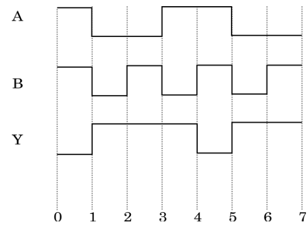
- The following figure shows the input waveforms (A, B) and the output waveform (Y) of a gate. Identify the gate, write its truth table and draw its logic symbol.