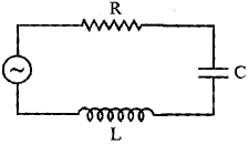
An inductor 200 mH, capacitor 500 µF, resistor 10Ω are connected in series with a100 V, variable frequency a.c. source. Calculate the
- Frequency at which the power factor of the circuit is unity.
- Current amplitude at this frequency.
- Q-factor.
CBSE DELHI - SET 1 2008
Download our app for free and get started
- $\omega = \frac{1}{\sqrt{\text{LC}}}$
$\big(\text{or } \text{ v} = \frac{\omega}{2\pi} = \frac{50}{\pi} \text{Hz}\approx51.9\text{Hz})$
- $\text{I} = \frac{\text{V}}{\text{R}} = \frac{100}{10} = 10 \text{A}$
- Q-factor $\frac{1}{\text{R}}\sqrt{\frac{\text{L}}{\text{C}}}$ $\big(\text{Q-factor } = \frac{\omega_{\circ}\text{L}}{\text{R}}\big)$

Download our appand get started for free
Experience the future of education. Simply download our apps or reach out to us for more information. Let's shape the future of learning together!No signup needed.*
Similar Questions
- 1View SolutionExplain why the reactance offered by an inductor increases with increasing frequency of an alternating voltage.
- 2View Solution
- Write the important properties of photons which are used to establish Einstein’s photoelectric equation.
- Use this equation to explain the concept of (i) threshold frequency and, (ii) Stopping potential.
- 3View Solution
- Explain briefly the process of emission of light by a Light Emitting Diode (LED).
- Which semiconductors are preferred to make LEDs and why?
- Give two advantages of using LEDs over conventional incandescent lamps.
- 4The figure shows a series LCR circuit with L = 5.0 H, C = 80 $\mu$F, R = 40 W connected to a variable frequency 240V source. CalculateView Solution
- The angular frequency of the source which drives the circuit at resonance.
- The current at the resonating frequency.
- The rms potential drop across the capacitor at resonance.
- 5View Solution
- Distinguish between a conductor and a semi conductor on the basis of energy band diagram.
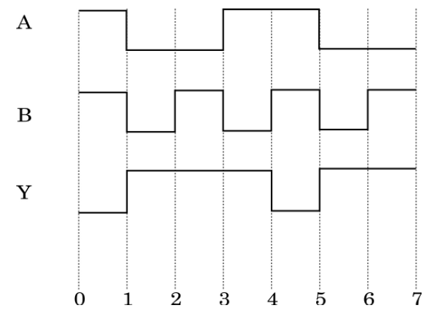
- The following figure shows the input waveforms (A, B) and the output waveform (Y) of a gate. Identify the gate, write its truth table and draw its logic symbol.
- 6A resistor R and an inductor L are connected in series to a source $\text{V}=\text{V}_0\sin\omega\text{t}.$View Solution
Find:- Peak value of the voltage drops across R and across L,
- Phase difference between the applied voltage and current. Which of them is ahead?
- 7View SolutionExplain briefly, with the help of a circuit diagram, the transistor action of npn transistor in CE configuration. Draw the typical shapes of input and output characteristics.
- 8Two capacitors of capacitance $10\mu\text{F}$ and $20 \mu\text{F}$ are connected in series with a 6 V battery. After the capacitors are fully charged, a slab of dielectric constant (K) is inserted between the plates of the two capacitors. How will the following be affected after the slab is introduced:View Solution
- The electric field energy stored in the capacitors.
- The charges on the two capacitors.
- The potential difference between the plates of the capacitors.
- 9View SolutionWrite two important considerations used while fabricating a Zener diode. Explain, with the help of a circuit diagram, the principle and working of a Zener diode as voltage regulator.
- 10View SolutionWhat is Global Positioning System? Explain its working principle in brief.