Write two important considerations used while fabricating a Zener diode. Explain, with the help of a circuit diagram, the principle and working of a Zener diode as voltage regulator.
CBSE OUTSIDE DELHI - SET 3 PATNA 2015
Download our app for free and get started
Two important considerations:
Heavy doping of both p and n sides.
Appropriate "break down voltage‟ under reverse bias.
Circuit diagram:
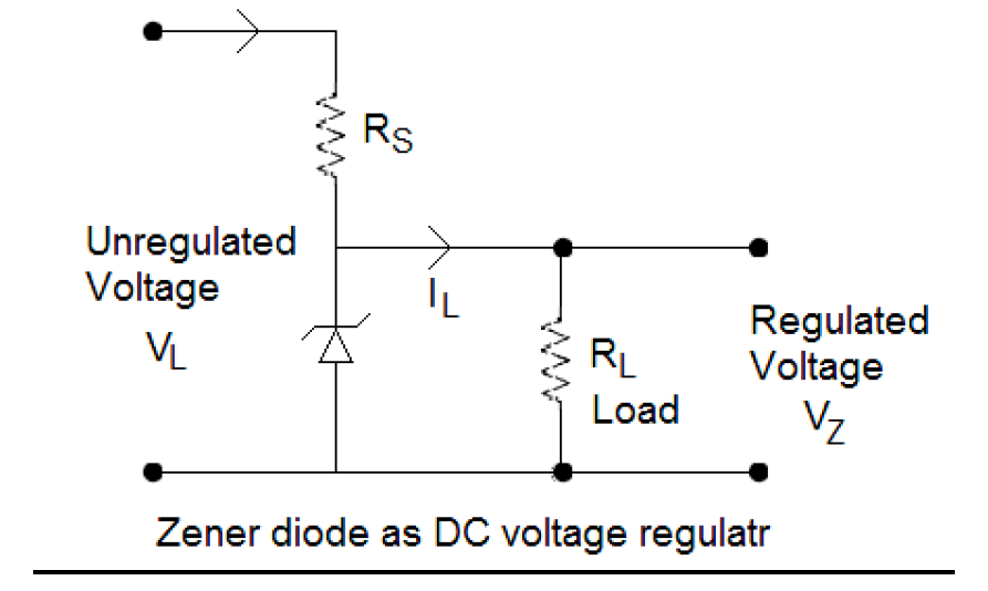
Principle: Even small reverse bias voltage (5V) can produce a very high electric field because the depletion region is very thin.
Working: The unregulated DC voltage is connected to the Zener diode through a series resistance RS such that the Zener diode is reverse biased. In breakdown region, the Zener voltage remains constant even though the current through Zener diode changes. This helps to regulate the output voltage.
Heavy doping of both p and n sides.
Appropriate "break down voltage‟ under reverse bias.
Circuit diagram:
Principle: Even small reverse bias voltage (5V) can produce a very high electric field because the depletion region is very thin.
Working: The unregulated DC voltage is connected to the Zener diode through a series resistance RS such that the Zener diode is reverse biased. In breakdown region, the Zener voltage remains constant even though the current through Zener diode changes. This helps to regulate the output voltage.

Download our appand get started for free
Experience the future of education. Simply download our apps or reach out to us for more information. Let's shape the future of learning together!No signup needed.*
Similar Questions
- 1View Solution
- Distinguish between a conductor and a semi conductor on the basis of energy band diagram.
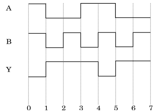
- The following figure shows the input waveforms (A, B) and the output waveform (Y) of a gate. Identify the gate, write its truth table and draw its logic symbol.
- 2A source of ac voltage $ v= v_0 \sin\omega t$, is connected across a pure inductor of inductance L. Derive the expressions for the instantaneous current in the circuit. Show that average power dissipated in the circuit is zero.View Solution
- 3View Solution
- For a glass prism $(\mu =\sqrt{3} )$ the angle of minimum deviation is equal to the angle of the prism. Calculate the angle of the prism.
- Draw ray diagram when incident ray falls normally on one of the two equal sides of a right angled isosceles prism having refractive index $\mu = \sqrt{3} . $
- 4A sinusoidal voltage of peak value $283 V$ and frequency $50 Hz$ is applied to a series $L C R$ circuit in which $R =3 \Omega, L=25.48 mH$, and $C =796 \mu F$. Find (a) the impedance of the circuit; (b) the phase difference between the voltage across the source and the current; (c) the power dissipated in the circuit; and (d) the power factor.View Solution
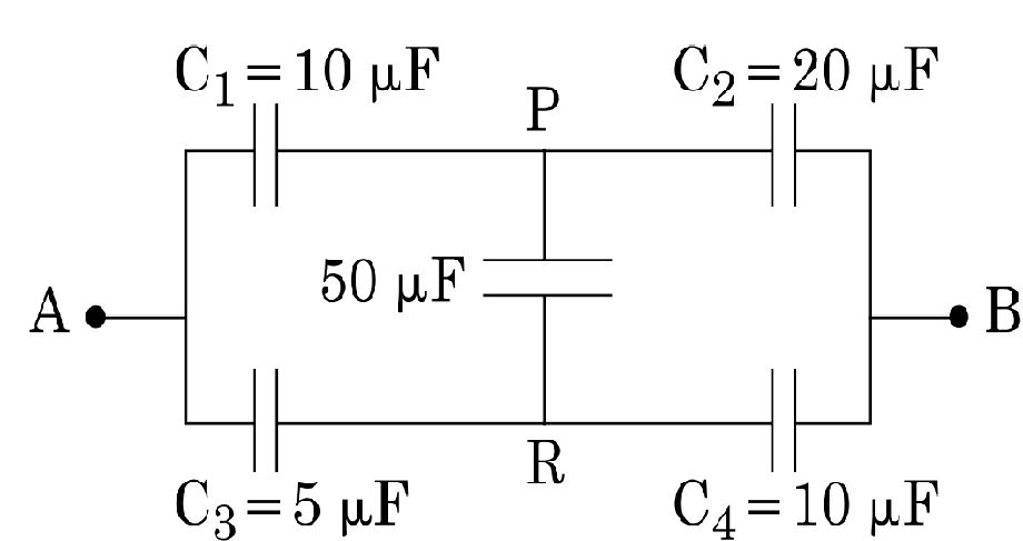
- 5View SolutionCalculate the equivalent capacitance between points A and B in the circuit below. If a battery of 10 V is connected across A and B, calculate the charge drawn from the battery by the circuit.
- 6View Solution
- Draw a schematic ray diagram of a compound microscope when image is formed at distance of distinct vision.
- Write the expression for resolving power of a compound microscope. How can the resolving power of a microscope be increased?
- 7View SolutionHow is a galvanometer converted into a voltmeter and an ammeter? Draw the relevant diagrams and find the resistance of the arrangement in each case. Take resistance of galvanometer as G.
- 8View SolutionA series LCR circuit with R = 20Ω, L = 1.5H and C = 35μF is connected to a variable-frequency 200V ac supply. When the frequency of the supply equals the natural frequency of the circuit, what is the average power transferred to the circuit in one complete cycle?
- 9View SolutionAn electric bulb is designed to operate at 12 volts DC. If this bulb is connected to an AC source and gives normal brightness, what would be the peak voltage of the source?
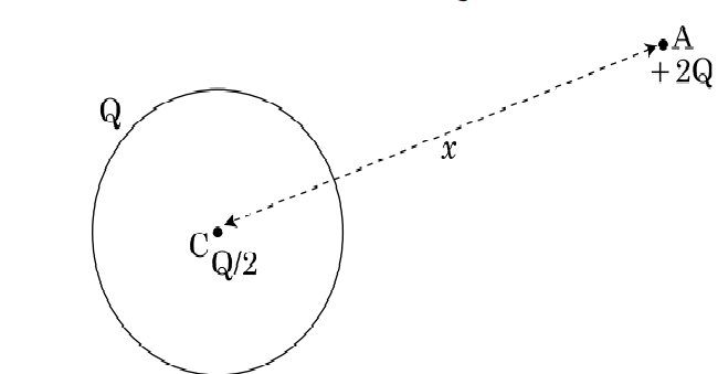
- 10View SolutionA thin metallic spherical shell of radius R carries a charge Q on its surface. A point charge Q/2 is placed at the centre C, and another charge + 2Q is placed outside the shell at A at a distance x from the centre as shown in the figure.
- Find the electric flux through the shell.
- State the law used.
- Find the force on the charges at the centre C of the shell and at the point A.