Assume a hypothetical wire in which free electron density changes with temperature in proportionality $n\ \alpha \ T$ assuming $\tau $(Relaxation time of collision) and dimensions of wire remain unchanged with increasing temperature. Which one of the resistance $v/s$ temperature graph is true
Medium
Download our app for free and get started
$R = \left( {\frac{{2lm}}{{{e^2}\tau A}}} \right)\frac{1}{n}$

Download our appand get started for free
Experience the future of education. Simply download our apps or reach out to us for more information. Let's shape the future of learning together!No signup needed.*
Similar Questions
- 1A wire of length ' $r$ ' and resistance $100 \Omega$ is divided into $10$ equal parts. The first $5$ parts are connected in series while the next $5$ parts are connected in parallel. The two combinations are again connected in series. The resistance of this final combination is:View Solution
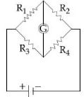
- 2The Wheatstone bridge shown in Fig. here, gets balanced when the carbon resistor used as $R_1$ has the colour code (Orange, Red, Brown). The resistors $R_2$ and $R_4$ are $80\, \Omega $ and $40\,\Omega $, respectively. Assuming that the colour code for the carbon resistors gives their accurate values, the colour code for the carbon resistor, used as $R_3$ would beView Solution
- 3To measure the internal resistance of a battery, potentiometer is used. For $\mathrm{R}=10 \Omega$, the balance point is observed at $\ell=500 \mathrm{~cm}$ and for $\mathrm{R}=1 \Omega$ the balance point is observed at $\ell=400 \mathrm{~cm}$. The internal resistance of the battery is approximately :View Solution
- 4In a potentiometer experiment the balancing with a cell is at length $240\, cm$. On shunting the cell with a resistance of $2$ $\Omega$, the balancing length becomes $120\, cm$. The internal resistance of the cell is ................. $\Omega $View Solution
- 5Two resistors of resistance, $100\,\Omega$ and $200\,\Omega$ are connected in parallel in an electrical circuit. The ratio of the thermal energy developed in $100\,\Omega$ to that in $200\,\Omega$ in a given time is:View Solution
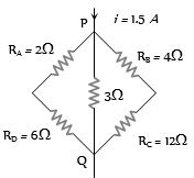
- 6Potential difference between the points $P$ and $Q$ in the electric circuit shown is ................. $V$View Solution
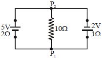
- 7A $5\, V$ battery with internal resistance $2\, \Omega$ and a $2\,V$ battery internal resistance $1\, \Omega$ are connected to a $10\, \Omega$ resistor as shown in the figure. The current in the $10\, \Omega$ resistor is :-View Solution
- 8If the resistivity of a potentiometer wire be $\rho $ and area of cross-section be $A$, then what will be potential gradient along the wireView Solution
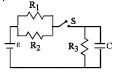
- 9The circuit shown in the figure consists of a battery of $emf$ $\varepsilon = 10 \,V$ ; a capacitor of capacitance $C = 1.0$ $ \mu F$ and three resistor of values $R_1 = 2$ $\Omega$ , $R_2 = 2$ $\Omega$ and $R_3 = 1$ $\Omega$ . Initially the capacitor is completely uncharged and the switch $S$ is open. The switch $S$ is closed at $t = 0.$View Solution
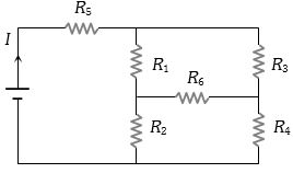
- 10In the given circuit, it is observed that the current $I$ is independent of the value of the resistance $R_6$. Then the resistance values must satisfyView Solution