Question
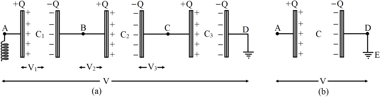
  1. Derive an expression for equivalent capacitance of three capacitors when connected in series.
  2. Derive an expression for equivalent capacitance of three capacitors when connected in parallel.

Answer

In fig. (a) Three capacitors of capacitances $C_1, C_2, C_3$ are connected in series between points A and D.
In 'series’ first plate of each capacitor has charge +Q and second plate of each capacitor has charge -Q
i.e., charge on each capacitor is Q. Let the potential differences across the capacitors $C_1, C_2, C_3$ be $V_1, V_2, V_3$ respectively.
As the second plate of first capacitor $C_1$ and first plate of second capacitor $C_2$ are connected together,
their potentials are equal. Let this common potential be $ V_B.$
Similarly the common potential of second plate of $C_2$ and first plate of $C_3$ is $V_C.$
The second plate of capacitor $C_3$ is connected to earth,
therefore its potential $V_D = 0$. As charge flows from higher potential to lower potential,
therefore $V_A > V_B > V_C > V_D.$ For the frist capacitor,
$\text{V}_1=\text{V}_\text{A}-\text{V}_\text{B}=\frac{\text{Q}}{\text{C}_1}\ ...(\text{i)}$
For the second capacitor, $\text{V}_1=\text{V}_\text{B}-\text{V}_\text{C}=\frac{\text{Q}}{\text{C}_2}\ ...(\text{ii)}$
For the third capacitor, $\text{V}_3=\text{V}_\text{C}-\text{V}_\text{D}=\frac{\text{Q}}{\text{C}_3}\ ...(\text{iii)}$ Adding (i), (ii) and (iii), we get, $\text{V}_1+\text{V}_2+\text{V}_3=\text{V}_\text{A}-\text{V}_\text{D}=\text{Q}\Big[\frac{1}{\text{C}_1}+\frac{1}{\text{C}_2}+\frac{1}{\text{C}_3}\Big]\ ...(\text{iv)}$
If V be the potential difference between A and D, then, $\text{V}_\text{A}-\text{V}_\text{D}=\text{V}$ $\therefore$ From (iv), we get, $\text{V}=\big(\text{V}_1+\text{V}_2+\text{V}_3=\text{Q}\Big[\frac{1}{\text{C}_1}+\frac{1}{\text{C}_2}+\frac{1}{\text{C}_3}\Big]\ ...(\text{v})$
If in place of all the three capacitors, only one capacitor is placed between A and D such that on giving it charge Q,
the potential difference between its plates become V,
then it will be called equivalent capacitor. If its capacitance is C,
then, $\text{V}=\frac{\text{Q}}{\text{C}}\ ...(\text{vi})$ Comparing (v) and (vi),
we get, $\frac{\text{Q}}{\text{C}}=\text{Q}\Big[\frac{1}{\text{C}_1}+\frac{1}{\text{C}_2}+\frac{1}{\text{C}_3}\Big]\ \text{Or}\ \frac{1}{\text{C}}=\frac{1}{\text{C}_1}+\frac{1}{\text{C}_2}+\frac{1}{\text{C}_3}$

Need a full question paper?

Generate a complete, print-ready paper with questions like this in minutes — across 16+ boards, with answer keys.

Start Generating Free

Similar questions

A multirange voltmeter can be constructed by using a galvanometer circuit as shown in Fig. We want to construct a voltmeter that can measure 2V, 20V and 200V using a galvanometer of resistance 10Ω and that produces maximum deflection for current of 1mA. Find $R_1, R_2$ and $R_3$ that have to be used.
The magnitude F of the force between two straight parallel current carrying conductors kept at a distance d apart in air is given by:
$\text{F}=\frac{\mu_0\text{I}_1\text{I}_2}{2\pi\text{d}}$
Where $I_1$ and $I_2$ are the currents flowing through the two wires.
Use this expression, and the sign convention that the:
“Force of attraction is assigned a negative sign and Force of repulsion is assigned a positive sign”.
Draw graphs showing dependence of F on:
  1. $I_1 I_2 $ when d is kept constant.
  2. d when the product $I_1 I_2$ is maintained at a constant positive value.
  3. d when the product $I_1 I_2$ is maintained at a constant negative value.
(a) Prove that the peak value ( $I_m$ ) of an alternating current is $\sqrt{2}$ times its root mean square ( rms ) value.(b) If alternating current $I=4 sin \omega t$ of and voltage $V =200 \sin (\omega t+\pi / 3)$, calculate the dissipated average power in the circuit.
In the arrangement shown in figure y = 1.0mm. d = 0.24mm end D = 1.2m. The work function of the materiel of the emitter is 2.2eV. Find the stopping potential V needed to stop the photocurrent.
  1. With the help of a labelled diagram, explain the working of a step-up transformer. Give reasons to explain the following:
  1. The core of the transformer is laminated.
  2. Thick copper wire is used in windings.
  1. A conducting rod PQ of length 20cm and resistance $0.1\Omega$ rests on two smooth parallel rails of negligible resistance AA' and CC'. It can slide on the rails and the arrangement is positioned between the poles of a permanent magnet producing uniform magnetic field B = 0.4T. The rails, the rod and the magnetic field are in three mutually perpendicular directions as shown in the figure. If the ends A and C of the rails are short circuited,
Find:
  1. External force required to move the rod with uniform velocity v = 10cm/ s,
  2. Power required to do so.
Two coils A and B have inductances 1.0H and 2.0H respectively. The resistance of each coil is $10\Omega.$ Each coil is connected to an ideal battery of emf 2.0V at t = 0 Let $i_A$  and $i_B$ be the currents in the two circuit at time t. Find the ratio $\frac{\text{i}_\text{A}}{\text{i}_\text{B}}$
  1. t = 100ms
  2. t = 200ms
  3. t = 1s.
Two car garages have a common gate which needs to open automatically when a car enters either of the garages or cars enter both. Devise a circuit that resembles this situation using diodes for this situation.
Two capacitors of capacitances 20.0pF and 50.0pF are connected in series with a 6.00V battery. Find:
  1. The potential difference across each capacitor.
  2. The energy stored in each capacitor.
A beam of white light is incident normally on a plane surface absorbing 70% of the light and reflecting the rest. If the incident beam carries 10W of power, find the force exerted by it on the surface.
k transparent slabs are arranged one over another. The refractive indices of the slabs are $\mu_1,\mu_2,\mu_3, \ ...\mu_{\text{k}}$ and the thicknesses are $t_1, t_2, t_3, ... t_k$ . An object is seen through this combination with nearly perpendicular light. Find the equivalent refractive index of the system which will allow the image to be formed at the same place.