Figure $(i)$ below shows a Wheatstone's bridge in which $P, Q, R$ and $S$ are fixed resistances, $G$ is a galvanometer and $B$ is a battery. For this particular case, the galvanometer shows zero deflection. Now, only the positions of $B$ and $G$ are interchanged, as shown in figure $(ii)$. The new deflection of the galvanometer
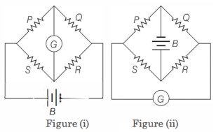
KVPY 2010, Medium


Download our appand get started for free
Experience the future of education. Simply download our apps or reach out to us for more information. Let's shape the future of learning together!No signup needed.*
Similar Questions
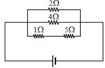
- 1A current of $3\,amp$ flows through the $2\,\Omega $ resistor shown in the circuit. The power dissipated in the $5\,\Omega $ resistor is ................. $watt$View Solution
- 2View SolutionKirchhoff's second law is based on the law of conservation of
- 3View SolutionThere are three resistance coils of equal resistance. The maximum number of resistances you can obtain by connecting them in any manner you choose, being free to use any number of the coils in any way is
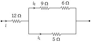
- 4In the following circuit, $5$ $\Omega$ resistor develops $45$ $J/s$ due to current flowing through it. The power developed per second across $12$ $\Omega$ resistor is ............. $W$View Solution
- 5An ammeter $A$ of finite resistance, and a resistor $R$ are joined in series to an ideal cell $C$. $A$ potentiometer $P$ is joined in parallel to $R$. The ammeter reading is $I_0$ and the potentiometer reading is $V_0$. $P$ is now replaced by a voltmeter of finite resistance. The ammeter reading now is $I$ and the voltmeter reading is $V$.View Solution

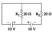
- 6In the given circuit the cells have zero internal resistance. The currents (in Amperes) passing through resistance $R_1$ and $R_2$ respectively, areView Solution
- 7Potential difference between the points $P$ and $Q$ in the electric circuit shown is ................. $V$View Solution
- 8A storage cell is charged by $5\, amp$ $D.C.$ for $18$ hours. Its strength after charging will be .............. $AH$View Solution
- 9In the circuit shown, the thermal power dissipated in $R_1$ is $P$. The thermal power dissipated in $R_2$ isView Solution
- 10Two cells when connected in series are balanced on $8\;m$ on a potentiometer. If the cells are connected with polarities of one of the cell is reversed, they balance on $2\,m$. The ratio of $e.m.f.$'s of the two cells isView Solution