Question
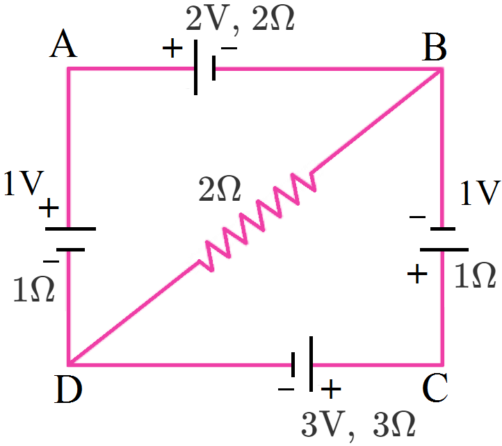
For the circuit shown here, calculate the potential difference between points B and D.

Answer

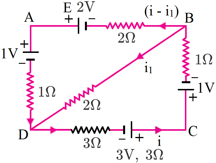
According to Kirchhoff’s first law the distribution of currents is shown in fig.

Applying Kirchhoff’s second law to mesh BADB,

–2(i – i1) +2 – 1 – 1. (i – i1) + 2i1 = 0

⇒ 3i – 5i1 = 1 …(i)

Applying Kirchhoff’s law to mesh DCBD,

-3i + 3 - 1 - 1× i - 2i1 = 0

⇒ 4i + 2i1 = 2

Or 2i + i1 = 1 …(ii)

Multiplying equation (ii) with 5, we get

10i + 5i1 = 5 …(iii)

Adding (i) and (iii), we get

$13\text{i}=6\Rightarrow\text{i}=\frac{6}{13}\text{A}$

From (ii), $\text{i}_1=1-2\text{i}=1-\frac{12}{13}=\frac{1}{13}\text{A}$

Potential difference between B and D is,

$\text{V}_\text{n}-\text{v}_\text{n}=\text{i}-1\times2=\frac{2}{13}\text{V}$

Need a full question paper?

Generate a complete, print-ready paper with questions like this in minutes — across 16+ boards, with answer keys.

Start Generating Free

Similar questions

Find the maximum magnitude of the linear momentum of a photoelectron emitted when light of wavelength 400 run falls on a metal having work function 2.5eV.
Define total internal reflection. Establish the relation between $u, v$ and $f$ for a spherical mirror. Draw the necessary ray diagram. ### Define lateral displacement. Derive the lens maker formula.
$
\frac{1}{f}=\left(n_{21}-1\right)\left(\frac{1}{R_1}-\frac{1}{R_2}\right)
$
Draw the necessary ray diagram. (Where the signs have their usual meanings.)
In the circuit shown in the figure. $\in_1=3\text{V},\in_2=2\text{V},\in_3=1\text{V}$ and $\text{r}_1=\text{r}_2=\text{r}_3=1\Omega.$ Find the potential difference between the points A and B and the current through each branch.

In the circuit shown in Fig., when the input voltage of the base resistance is 10V, Vbe is zero and Vce is also zero. Find the values of Ib, Ic and β.

ODBAC is a fixed rectangular conductor of negilible resistance (CO is not connnected) and OP is a conductor which rotates clockwise with an angular velocity $\omega$ (Fig). The entire system is in a uniform magnetic field B whose direction is along the normal to the surface of the rectangular conductor ABDC. The conductor OP is in electric contact with ABDC. The rotating conductor has a resistance of $\lambda$ per unit length. Find the current in the rotating conductor, as it rotates by 180º.

A small plane area is rotated in an electric field. In which orientation of the area is the flux of electric field through the area maximum? In which orientation is it zero?
The flux of magnetic field through a closed conducting loop changes with time according to the equation, $\phi=\text{at}^2+\text{bt}+\text{c}.$
  1. Write the SI units of a, band c.
  2. If the magnitudes of a, b and c are 0.20, 0.40 and 0.60 respectively, find the induced emf at t = 2s.
Use (i) the Ampere's law for H and (ii) continuity of lines of B, to conclude that inside a bar magnet, (a) lines of H run from the N pole to S pole, while (b) lines of B must run from the S pole to N pole.
If the resistance R1 is increased (Fig.), how will the readings of the ammeter and voltmeter change?

The magnetic field in the cylindrical region shown in figure increases at a constant rate of 20.0mT/s. Each side of the square loop abcd and defa has a length of 1.00cm and a resistance of $4.00\Omega.$ Find the current (magnitude and sense) in the wire ad if:

  1. The switch S1 is closed but S2 is open.
  2. S1 is open but S2 ia closed.
  3. Both S1 and S2 are open.
  4. Both S1 and S2 are closed.