Question
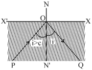
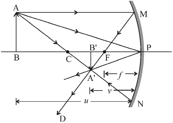
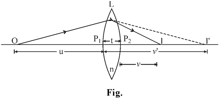
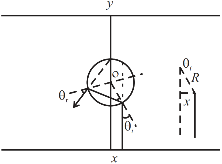
Define total internal reflection. Establish the relation between $u, v$ and $f$ for a spherical mirror. Draw the necessary ray diagram. ### Define lateral displacement. Derive the lens maker formula.
$
\frac{1}{f}=\left(n_{21}-1\right)\left(\frac{1}{R_1}-\frac{1}{R_2}\right)
$
Draw the necessary ray diagram. (Where the signs have their usual meanings.)

Answer

Total Internal Reflection : When the value of the angle of incidence in a dense medium is increased slightly beyond the critical angle, then the entire incident light gets reflected according to the laws of reflection and returns back to the dense medium. As shown in the fig. below. This phenomenon is called total internal reflection of light.
Image
Fig. : Total internal reflection
Relation between $u, v$ and $f$ for the Spherical Mirror :
Formula for spherical mirror :
The relationship between $u, v$ and $f$ is shown in the figure to form an image from a concave mirror. At point B on the principal axis, a parallel ray AM from the object AB hits the surface of the mirror AM and passes through the focus after reflection. Ray AC from point A hits the mirror and returns to the same path due to being normal. These two reflected rays meet each other at point $A^{\prime}$. Hence the image of $A B$ becomes $B ^{\prime} A ^{\prime}$. Draw lines joining AP and AP . In the figure $\triangle MPF$ and $\triangle A ^{\prime} F ^{\prime} B , \angle A ^{\prime} FB ^{\prime}=\angle MFP$ due to opposite angle (mirror is of small aperture) hence MP is a straight line.
Since $\angle FPM =\angle A ^{\prime} FB B ^{\prime}$ is a right angle, so due to which $\triangle MPF , \triangle AF ^{\prime} B ^{\prime}$ is a similar triangle.
Therefore,$\frac{B^{\prime} A^{\prime}}{PM}=\frac{B^{\prime} F}{FP}$
$
\text { or } \quad \frac{B^{\prime} A^{\prime}}{BA}=\frac{B^{\prime} F}{FP}(\because PM=AB) \ldots(1)
$
Because $\angle APB =\angle APB ^{\prime}$, right angled triangles ABP and ABP are also similar.
Therefore, $\quad \frac{ B ^{\prime} A ^{\prime}}{ BA }=\frac{ B ^{\prime} P }{ BP } \ldots(2) $
By comparing equation (1) and (2), we will get
$
\frac{B^{\prime} F}{F P}=\frac{B^{\prime} P-F P}{F P}=\frac{B^{\prime} P}{B P} \ldots(3)
$
Equation (3) involves the magnitudes of distances. According to Cartesian sign convention, the signs of these three will be negative, hence
$
B^{\prime} P=-v, FP=-f, BP=-u
$
Image
Fig. : Ray diagram of image formation by a concave mirror
Using these in equation (3), we get
$\frac{-v+f}{-f}=\frac{-v}{-u}$
or $\quad \frac{v-f}{f}=\frac{v}{u}$
$\frac{v}{f}-1=\frac{v}{u}$
or $\quad\frac{v}{f}=\frac{v}{u}+1=\frac{v+u}{u}$
or $\quad \frac{1}{f}=\frac{v+u}{u v}=\frac{v}{u v}+\frac{u}{u v}$
or $\quad \frac{1}{v}+\frac{1}{u}=\frac{1}{f}$ $\ldots(4)$
This relation is called mirror equations
OR

A ray of light travels in a definite straight line. After refraction through the glass slab, it emerges in a direction parallel to the original direction but slightly displaced from the line. This is called lateral displacement.
When the medium on either side of the lens is same : In the following figure, a thin lens L is placed in the air. Refractive index of the lens material relative to air is $n$ and the radii of curvature of its first and second surfaces are $R _1$ and $R _2$ respectively. Let the thickness of the lens be $t$.
Image
A point object $O$ is placed on the principal axis of the lens at a distance $u$ from the pole $P _1$ of its first surface. Due to refraction on the first surface, the image of object $O$ is formed at $I ^{\prime}$. Let the distance of $I ^{\prime}$ from the pole $P _1$ of the surface be $v^{\prime}$. Then according to the formula of refraction at a single spherical surface
$
\frac{n}{v^{\prime}}-\frac{1}{u}=\frac{n-1}{R_1} \ldots(1)
$
The image thus formed is $I^{\prime}$ for the second surface of the lens whose radius of curvature is $R _2$ will work as an object. The distance of I' from the pole $P _2$ of the other surface will be $\left(v^{\prime}-t\right)$. The image of second surface of I is I' at a distance from $v$. In this way the final image of the O of entire lens becomes at I .
On the second surface, because the light ray enters the air through the refractive index $n$, hence in the formula of refraction, writin $1 / n$ at place of $n$.
$
\frac{1 / n}{v}-\frac{1}{\left(v^{\prime}-1\right)}=\frac{\frac{1}{n}-1}{R_2} \ldots(2)
$
For thin lenses. The value of $t$ is negligible compared to $v^{\prime}$. So in comparison of $v$, on omitting $t$, the equation (2) will be as follows :
$\frac{1}{v}-\frac{n}{v^{\prime}}=\frac{-(n-1)}{ R _2} \ldots(3) $
By adding equations (1) and (3)
$
\frac{1}{v}-\frac{1}{u}=(n-1)\left(\frac{1}{R_1}-\frac{1}{R_2}\right) \ldots(4)
$
When the object is placed at infinity, the image will be formed at the second focus (principal focus) of the lens. That is $u=\infty$, then $v=f$, where $f$ is the second focal length (primary focal length) of the lens.
Putting the value in equation (4)
$
\frac{1}{f}-\frac{1}{\infty}=(n-1)\left(\frac{1}{R_1}-\frac{1}{R_2}\right)
$
or $\quad \frac{1}{f}=(n-1)\left(\frac{1}{R_1}-\frac{1}{R_2}\right) \ldots(5) $
Which is called lens makers formula.

Need a full question paper?

Generate a complete, print-ready paper with questions like this in minutes — across 16+ boards, with answer keys.

Start Generating Free

Similar questions

An infinitely long cylinder of radius R is made of an unusual exotic material with refractive index -1 (Fig). The cylinder is placed between two planes whose normals are along the y direction. The center of the cylinder O lies along the y-axis. A narrow laser beam is directed along the y direction from the lower plate. The laser source is at a horizontal distance x from the diameter in the y direction. Find the range of x such that light emitted from the lower plane does not reach the upper plane.

Write Einstein's photoelectric equation and explain any two observations related to the photoelectric effect.
A particle with a charge of 5.0 µC and a mass of 5.0 × 10⁻¹²kg is projected with a speed of 1.0km s-1 in a magnetic field of magnitude 5.0mT. The angle between the magnetic field and the velocity is sin-1 (0.90). Show that the path of the particle will be a helix. Find the diameter of the helix and its pitch.
Two wires are kept tight between the same pair of supports. The tensions in the wires are in the ratio 2 : 1, the radii are in the ratio 3 : 1 and the densities are in the ratio 1 :2. Find the ratio of their fundamental frequencies.
Consider the situation of the previous problem. Consider the fastest electron emitted parallel to the large metal plate. Find the displacement of this electron parallel to its initial velocity before it strikes the large metal plate.
Determine the current in each branch of the network shown in Fig. 3.17.
Image
Consider a wire of length 4m and cross-sectional area 1mm2 carrying a current of 2A. If each cubic metre of the material contains 1029 free electrons, find the average time taken by an electron to cross the length of the wire.
A long wire carrying a current i is bent to form a plane angle $\alpha.$ Find the magnetic field B at a point on the bisector of this angle situated at a distance x from the vertex.
Fe+ ions are accelerated through a potential difference of 500V and are injected normally into a homogeneous magnetic field B of strength 20.0mT. Find the radius of the circular paths followed by the isotopes with mass numbers 57 and 58. Take the mass of an ion = A (1.6 × 10⁻²⁷)kg, where A is the mass number.
Consider the situation of the previous problem. Consider the fastest electron emitted parallel to the large metal plate. Find the displacement of this electron parallel to its initial velocity before it strikes the large metal plate.