Question 15 Marks
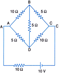
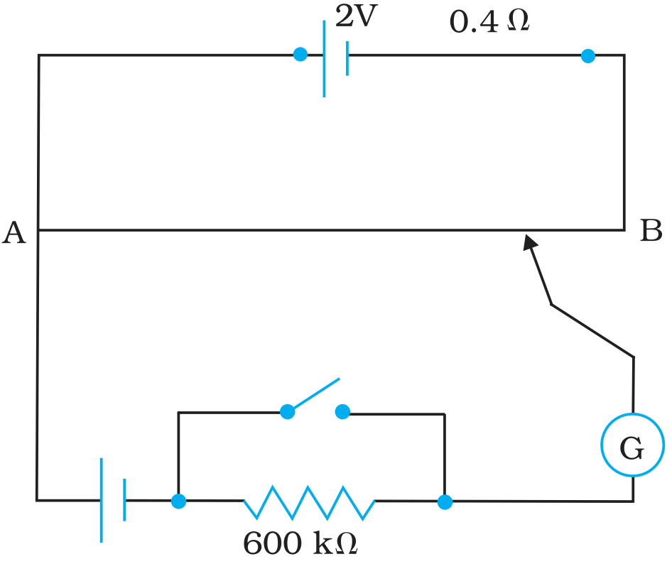
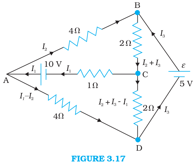
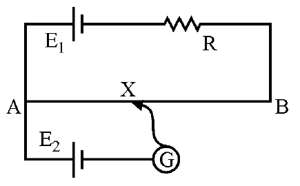
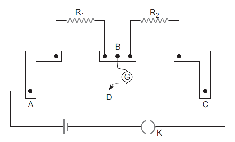
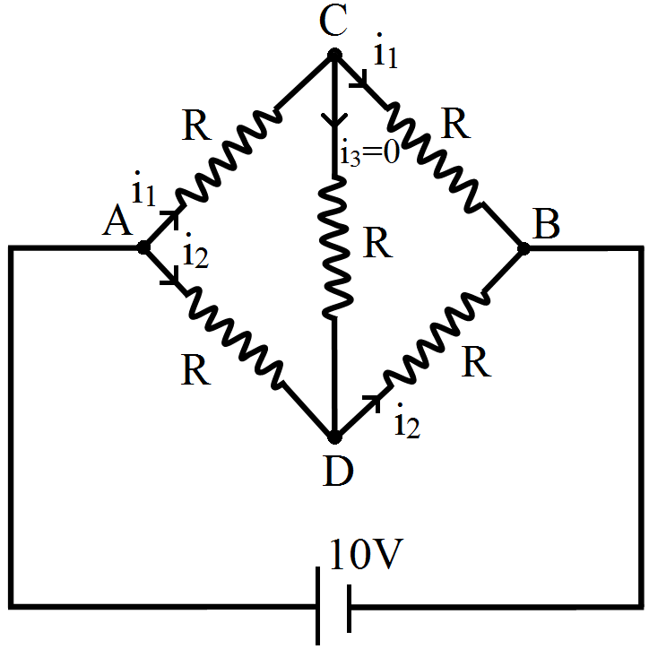
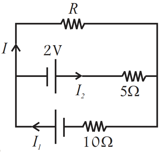
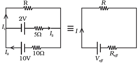
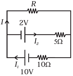
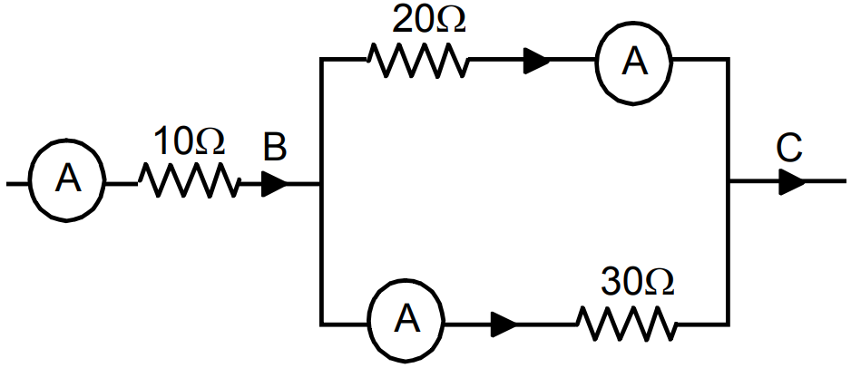
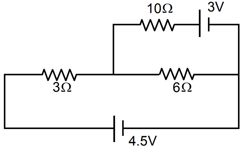
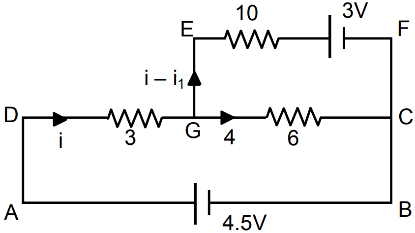
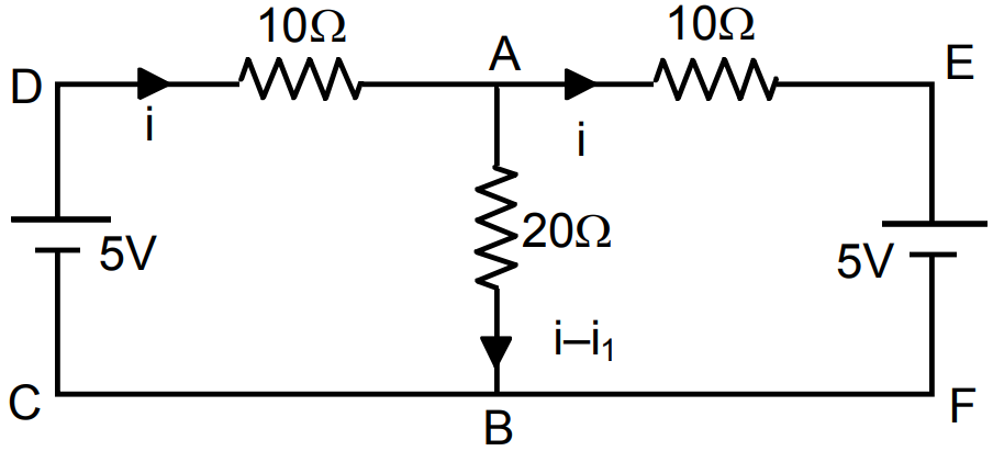
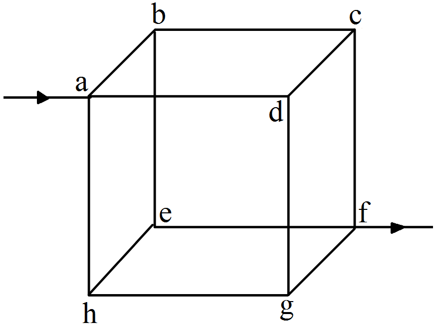
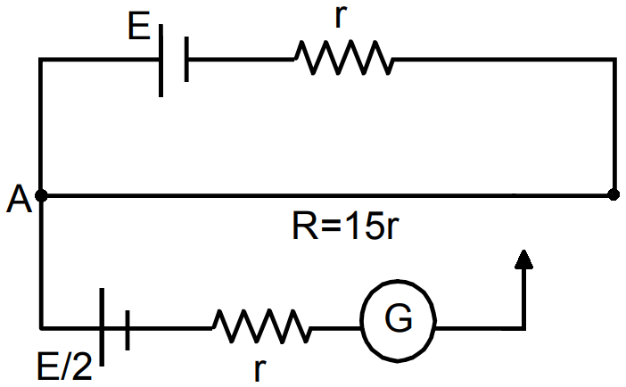
Determine the current in each branch of the network shown in Fig.:
Answer
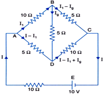
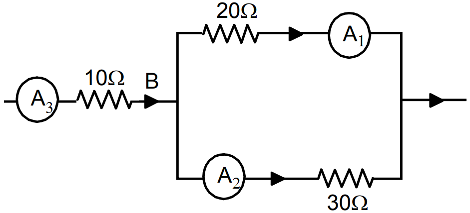
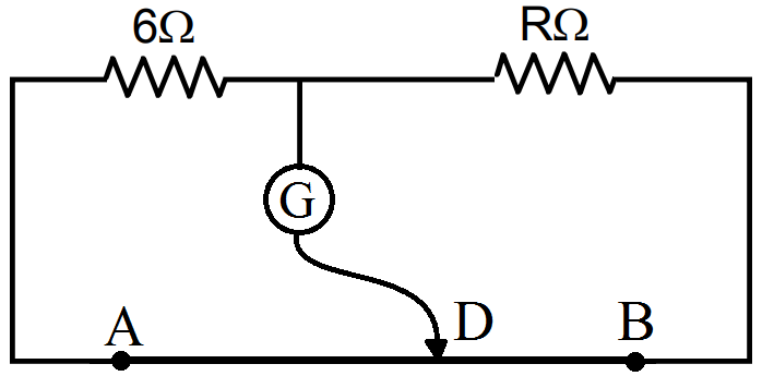
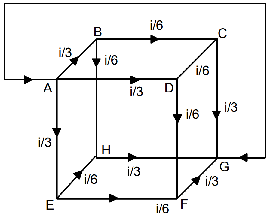
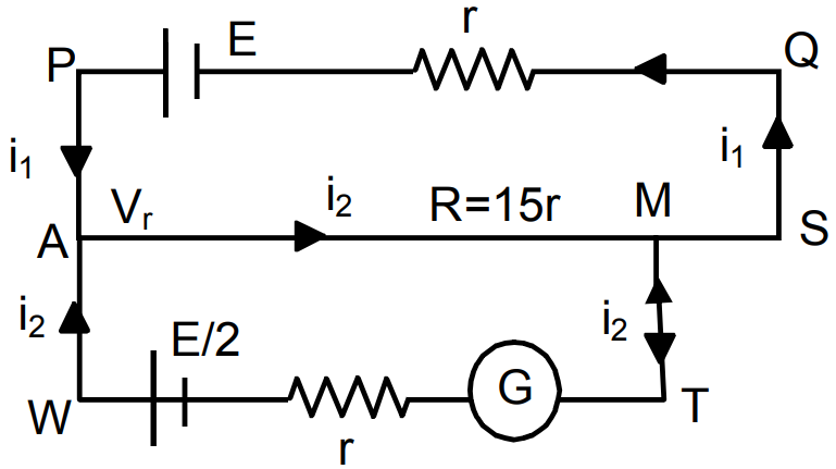
View full question & answer→Consider the mesh ABDA, Now, Applying Kirchhoff's loop rule we get, $-10\text{I}_1-5\text{I}_\text{g}+(\text{I}-\text{I}_1)5=0$ $\Rightarrow\ \ 3\text{I}_1-\text{I}+\text{I}_\text{g}=0\ \ ...\text{(i)}$


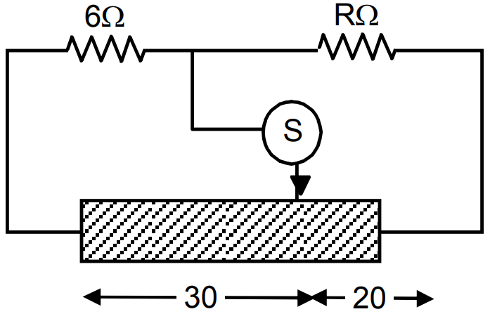

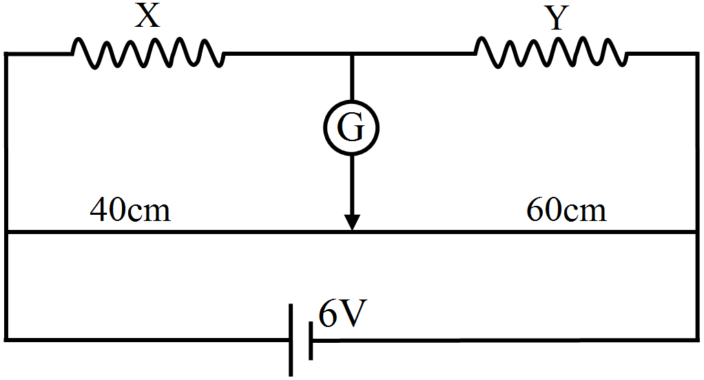
 For length x,
