If a copper wire is stretched to increase its length by $20 \% $. The percentage increase in resistance of the wire is $..........\%$
JEE MAIN 2023, Medium


Download our appand get started for free
Experience the future of education. Simply download our apps or reach out to us for more information. Let's shape the future of learning together!No signup needed.*
Similar Questions
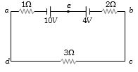
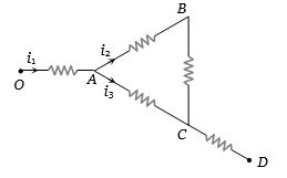
- 1View SolutionThe magnitude and direction of the current in the circuit shown will be
- 2A null point is found at $200\,cm$ in potentiometer when cell in secondary circuit is shunted by $5\,\Omega$. When a resistance of $15\,\Omega$ is used for shunting null point moves to $300\,cm$. The internal resistance of the cell is $..............\,\Omega$.View Solution
- 3Masses of three wires of copper are in the ratio of $1 : 3 : 5$ and their lengths are in the ratio of $5:3:1.$ The ratio of their electrical resistances areView Solution
- 4A storage battery has $e.m.f.$ $15\, volts$ and internal resistance $0.05\, ohm$. Its terminal voltage when it is delivering $10\, ampere$ is ............... $volts$View Solution
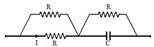
- 5View SolutionThe capacitor shown in fig. is in steady state. The energy stored in the capacitor is
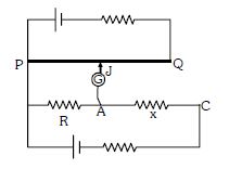
- 6Circuit for the measurement of resistance by potentiometer is shown. The galvanometer is first connected at point $A$ and zero deflection is observed at length $P J = 10\ cm$ . In second case it is connected at point $C$ and zero deflection is observed at a length $30\ cm$ from $P$ . Then the unknown resistance $X$ isView Solution
- 7A potentiometer wire, $10\,m$ long, has a resistance of $40\,\Omega $. It is connected in series with a resistance box and a $2\,V$ storage cell. If the potential gradient along the wire is $0.1\,m\,V/cm$, the resistance unplugged in the box is .............. $\Omega$View Solution
- 8The current in the arm $CD$ of the circuit will beView Solution
- 9The total power dissipated in watts in the circuit shown is ............. $W$View Solution
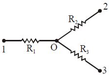
- 10.............. $A$ the current flowing through the resistance $R_2$ of the circuit shown in fig if the resistance are equal to $R_1 = 20\ \Omega, R_2 = 30 \ \Omega$ and $R_3 = 60 \ \Omega$ and potentials of points $1, 2$ and $3$ are equal to $V_1= 20\, V,$ $V_2 = 30\ V$ and $V_3 = 60\ V$View Solution