In Circuit-$1$ and Circuit- $2$ shown in the figures, $R_1=1 \Omega, R_2=2 \Omega$ and $R_3=3 \Omega$. $P_1$ and $P_2$ are the power dissipations in Circuit-$1$ and Circuit-$2$ when the switches $S_1$ and $S_2$ are in open conditions, respectively. $Q_1$ and $Q_2$ are the power dissipations in Circuit-$1$ and Circuit-$2$ when the switches $S_1$ and $S_2$ are in closed conditions, respectively.
Which of the following statement($s$) is(are) correct?
$(A)$ When a voltage source of $6 V$ is connected across $A$ and $B$ in both circuits, $P_1$
$(B)$ When a constant current source of $2 Amp$ is connected across $A$ and $B$ in both circuits, $P_1>P_2$.
$(C)$ When a voltage source of $6 V$ is connected across $A$ and $B$ in Circuit-$1$, $Q_1>P_1$.
$(D)$ When a constant current source of $2 Amp$ is connected across $A$ and $B$ in both circuits, $Q_2$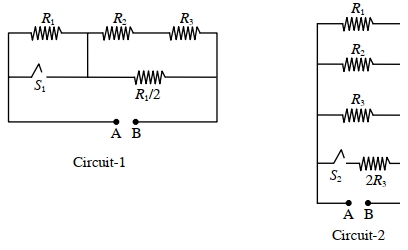
IIT 2022, Advanced
Download our app for free and get started
Case $(i)$
When both switches are open equivalent resistance in circuit $1$
$R _{ c _1}=\frac{16}{11} \Omega$
Equivalent resistance in circuit $2$
$R_{c=}=\frac{6}{11} \Omega$
For voltage source
$P=\frac{V^2}{R}$
$P \propto \frac{1}{R}$
$R_{c_e}>R_{c_e}$
$\Rightarrow P_2>P_1 \text { (Option (A) correct) }$
For congtant curent source
$P =i^2 R$
$P \propto R$
$\Rightarrow P _1> P _2 \text { (Option (B) coerect) }$
Cros-$II$
When swirch is cloced
$R _{c_1}^{\prime}=\frac{5}{11} \Omega$
$R _{c_1}^{\prime}=\frac{1}{2} \Omega$
$R _{c_0}^{\prime}< R _{c_0}$
For voltage source
$P \times \frac{1}{ R } \Rightarrow Q_2> P _2 \text { (Oprion (C) correct) }$
$ R_{c_0}^{\prime}>R_{c_1}^{\prime}$
For current source $P \propto R$.
$Q_1>Q_2 \text { (Option (D) also comrect) }$

Download our appand get started for free
Experience the future of education. Simply download our apps or reach out to us for more information. Let's shape the future of learning together!No signup needed.*
Similar Questions
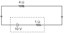
- 1The terminal voltage of the battery, whose emf is $10 \mathrm{~V}$ and internal resistance $1 \Omega$, when connected through an external resistance of $4 \Omega$ as shown in the figure is:View Solution
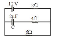
- 2Find the maximum charge on the capacitor $C$ in the following circuit ............ $\mu C$View Solution
- 3The combination of two identical cells, whether connected in series or parallel combination provides the same current through an external resistance of $2 \,\Omega$. The value of internal resistance of each cell is ............ $\Omega$View Solution
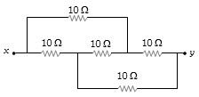
- 4The equivalent resistance between $x$ and $y$ in the circuit shown is ............. $\Omega$View Solution
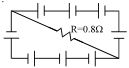
- 5$\mathrm{A}$ circuit is comprised of eight identical batteries and a resistor $R = 0.8\,\Omega$ . Each battery has an $\mathrm{emf}$ of $1.0\, V$ and internal resistance of $0.2\,\Omega$ . The voltage difference across any of the battery is ............. $V$View Solution
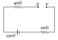
- 6Potential difference across the $40\,\Omega $ resistance will be ............ $V$View Solution
- 7Two resistances of $400$ $\Omega$ and $800$ $\Omega$ are connected in series with $6\, volt$ battery of negligible internal resistance. A voltmeter of resistance $10,000$ $\Omega$ is used to measure the potential difference across $400$ $\Omega$. The error in the measurement of potential difference in volts approximately isView Solution
- 8The resistance of a wire of uniform diameter $d$ and length $L$ is $R$. The resistance of another wire of the same material but diameter $2d$ and length $4L$ will beView Solution
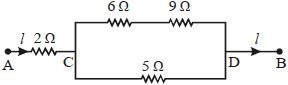
- 9In the circuit shown in figure, the $5\,\Omega $ resistance develops $20.00\,cal/s$ due to the current flowing through it. The heat developed in $2\,\Omega $ resistance (in $cal/s$ ) isView Solution
- 10In the given circuit diagram when the current reaches steady state in the circuit, the charge on the capacitor of capacitance $C$ will beView Solution