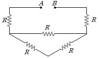
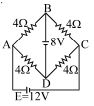
In the circuit shown in the figure below, which of the following statement is incorrect ?
Medium
Download our app for free and get started
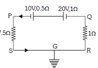
The equivalent circuit can be drawn :
$\mathrm{V}_{\mathrm{p}}=7 \mathrm{\,V}$
$\mathrm{V}_{\mathrm{q}}=-1 \mathrm{\,V}$
$\mathrm{V}_{\mathrm{S}}=\mathrm{V}_{\mathrm{R}}=0 \mathrm{\,V}$

Download our appand get started for free
Experience the future of education. Simply download our apps or reach out to us for more information. Let's shape the future of learning together!No signup needed.*
Similar Questions
- 1View SolutionThe conductivity of a superconductor is
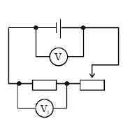
- 2If the rheostat slider were to move from the extreme right to the far left, How will the reading of voltmeter $V_1$ change?View Solution
- 3In a potentiometer circuit a cell of $EMF$ $1.5\, {V}$ gives balance point at $36\, {cm}$ length of wire. If another cell of $EMF$ $2.5\, {V}$ replaces the first cell, then at what length of the wire, the balance point occurs ? (in $cm$)View Solution
- 4By which of the following single load resistance the load bridge should be replaced so that the power to the load remains unchanged ................ $\Omega$View Solution
- 5Find the number of photons emitted per second from of source of light which results in a photocurrent with drift velocity of $1.5\ m/s$ in a conductor with cross-section area $0.25\ m^2$ , volume density of electrons $10^{20}\ per \ m^3$ , (Assume that $60\%$ of photons emitted result in electron emission)View Solution
- 6The given figure shows $a$ network of resistances and $a$ battery. Identify the correct statement $(s)$View Solution
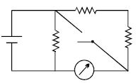
- 7In the circuit shown, the reading of the Ammeter is doubled after the switch is closed. Each resistor has a resistance $ = 1\,\Omega $ and the ideal cell has an $e.m.f. = 10\, V$. Then, the Ammeter has a coil resistance equal to ................ $\Omega$View Solution
- 8Give colors of the ring in sequence marked on a resistance of $56 \ k\Omega$ with tolerance $\pm 5\%$View Solution
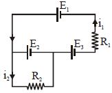
- 9The current $i_1$ and $i_2$ through the resistor $R_1 (= 10\,\Omega )$ and $R_2 (=30 \,\Omega )$ in the circuit diagram with $E_1 = 3\,V, E_2 = 3\,V$ and $E_3 = 2\,V$ are respectively:View Solution
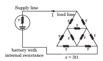
- 10What is the equivalent resistance between $A$ and $B$ in the figure below if $R = 3\,\Omega $View Solution