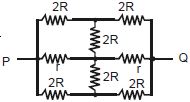
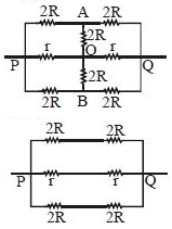
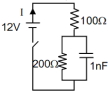
The effective resistance between points $P$ and $Q$ of the electrical circuit shown in the figure is
AIIMS 2013, Medium


Download our appand get started for free
Experience the future of education. Simply download our apps or reach out to us for more information. Let's shape the future of learning together!No signup needed.*
Similar Questions
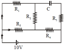
- 1An ideal cell of emf $10\, V$ is connected in circuit shown in figure. Each resistance is $2\, \Omega .$ The potential difference (in $V$) across the capacitor when it is fully charged isView Solution
- 2View SolutionCurrent provided by a battery is maximum when
- 3Four resistances $10$ $\Omega$, $5$ $\Omega$, $7$ $\Omega$ and $3$ $\Omega$ are connected so that they form the sides of a rectangle $AB$, $BC$, $CD$ and $DA$ respectively. Another resistance of $10$ $\Omega$ is connected across the diagonal $AC$. The equivalent resistance between $A$ and $B $ is .............. $\Omega$View Solution
- 4Find the charge in steady state of the capacitor. (in $nC)$View Solution
- 5A student has $10$ resistors of resistance ‘$r$’. The minimum resistance made by him from given resistors isView Solution
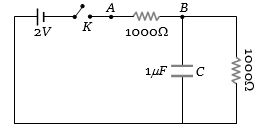
- 6When the key $K$ is pressed at time $t = 0$, which of the following statements about the current $I$ in the resistor $AB$ of the given circuit is trueView Solution
- 7View SolutionLamps used for household lighting are connected in
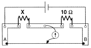
- 8A meter bridge is set-up as shown, to determine an unknown resistance ' $X$ ' using a standard $10$ ohm resistor. The galvanometer shows null point when tapping-key is at $52 \ cm$ mark. The end-corrections are $1 \ cm$ and $2 \ cm$ respectively for the ends $A$ and $B$. The determined value of ' $X$ ' isView Solution
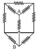
- 9Effective resistance between points $A$ and $B$ for following network is (each branch of resistance is $R$)View Solution
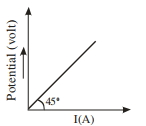
- 10The variation of applied potential and current flowing through a given wire is shown in figure. The length of wire is $31.4 \,cm$. The diameter of wire is measured as $2.4 \,cm$. The resistivity of the given wire is measured as $x \times 10^{-3} \,\Omega cm$. The value of $x$ is_______ [Take $\pi=3.14]$View Solution