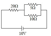
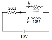
The ratio of heat dissipated per second through the resistance $5 \Omega$ and $10 \Omega$ in the circuit given below is: :
JEE MAIN 2024, Diffcult


Download our appand get started for free
Experience the future of education. Simply download our apps or reach out to us for more information. Let's shape the future of learning together!No signup needed.*
Similar Questions
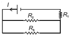
- 1Refer to the circuit shown. What will be the total power dissipation in the circuit if $P$ is the power dissipated in $R_1$ ? It is given that $R_2=4 R_1$ and $R_3=12 R_1$ are .......... $P$View Solution
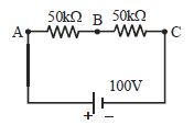
- 2In the adjacent shown circuit, a voltmeter of internal resistance $R$, when connected across $B$ and $C$ reads $\frac{{100}}{3}\,V$. Neglecting the internal resistance of the battery, the value of $R$ is ................. $k \Omega$View Solution
- 3View SolutionConductivity increases in the order of
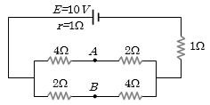
- 4In the circuit shown below, the cell has an $e.m.f.$ of $10\,V$ and internal resistance of $1\, ohm$. The other resistances are shown in the figure. The potential difference ${V_A} - {V_B}$ is ................ $V$View Solution
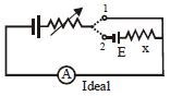
- 5In the circuit shown the variable resistance is so adjusted that the ammeter reading is same in both the position $1$ and $2$ of the key. The reading of ammeter is $2A$. If $E = 20V$, then $x$ is :- ................... $\Omega$View Solution
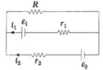
- 6View SolutionSee the electrical circuit shown in this figure. Which of the following equations is a correct equation for it ?
- 7The given figure shows $a$ network of resistances and $a$ battery. Choose the correct statement $(s)$.View Solution
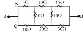
- 8In the arangement of resistances shown below, the effective resistance between points $A$ and $B$ is ............... $\Omega$View Solution
- 9View SolutionWhich of the following is vector quantity
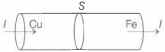
- 10Two rods of copper and iron with the same cross-sectional area are joined at $S$ and a steady current $I$ flows through the rods as shown in the figure. Choose the most appropriate representation of charges accumulated near the junction $S$.View Solution