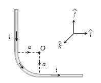
The unit vectors $\hat i,\;\hat j\;{\rm{and }}\,\hat k$ are as shown below. What will be the magnetic field at $O$ in the following figure
Diffcult
Download our app for free and get started
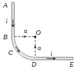
(d) The field at $O$ due to $AB$ is $\frac{{{\mu _0}}}{{4\pi }}.\frac{i}{a}\hat k$ and that due to $DE$ is also $\frac{{{\mu _0}}}{{4\pi }}.\frac{i}{a}\hat k$.
However the field due to $BCD$ is $\frac{{{\mu _0}}}{{4\pi }}.\frac{i}{a}\left( {\frac{\pi }{2}} \right)\,\hat k$.
Thus the total field at $O$ is $\frac{{{\mu _0}}}{{4\pi }}.\frac{i}{a}\left( {2 + \frac{\pi }{2}} \right)\,\hat k$
However the field due to $BCD$ is $\frac{{{\mu _0}}}{{4\pi }}.\frac{i}{a}\left( {\frac{\pi }{2}} \right)\,\hat k$.
Thus the total field at $O$ is $\frac{{{\mu _0}}}{{4\pi }}.\frac{i}{a}\left( {2 + \frac{\pi }{2}} \right)\,\hat k$

Download our appand get started for free
Experience the future of education. Simply download our apps or reach out to us for more information. Let's shape the future of learning together!No signup needed.*
Similar Questions
- 1In the given figure an ammeter $A$ consists of a $240 \Omega$ coil connected in parallel to a $10 \Omega$ shunt. The reading of the ammeter is . . . . . . $\mathrm{mA}$.View Solution
- 2An ammeter and a voltmeter of resistance $R$ are connected in series to an electric cell of negligible internal resistance. Their readings are $A$ and $V$ respectively. If another resistance $R$ is connected in parallel with the voltmeterView Solution
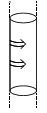
- 3A hollow cylinder having infinite length and carrying uniform current per unit length $\lambda$ along the circumference as shown. Magnetic field inside the cylinder isView Solution
- 4Two long and parallel wires are at a distance of $0.1\, m$ and a current of $5\, A$ is flowing in each of these wires. The force per unit length due to these wires will beView Solution
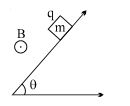
- 5A block of mass $m$ $\&$ charge $q$ is released on a long smooth inclined plane magnetic field $B$ is constant, uniform, horizontal and parallel to surface as shown. Find the time from start when block loses contact with the surface.View Solution
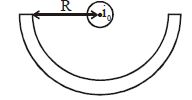
- 6Adjoining figure shows a very long semicylindrical conducting shell of radius $R$ and carrying a current $i$. An infinitely long straight current carrying conductor is lying along the axis of the semi-cylinder. If the current flowing through the straight wire be $i_0$, then the force per unit length on the conducting wire isView Solution
- 7Two very long straight parallel wires, parallel to $y-$ axis,carrycurrents $4I$ and $I,$ along $+y$ directionand$-y$ direction, respectively. The wires are passes through the $x-$axis at the points $(d, 0, 0)$ and $(- d, 0, 0)$ respectively.The graph of magnetic field $z-$component as one moves along the $x-$axis from $x=- d$ to $x= +d,$ is best given byView Solution
- 8If wire of length $L$ form a loop of radius $R$ and have $n$ turn. Find magnetic field at centre of loop if current flowing in loop is $I$View Solution
- 9Current $I$ is flowing in conductor shaped as shown in the figure. The radius of the curved part is $r$ and the length of straight portion is very large. The value of the magnetic field at the centre $O$ will beView Solution
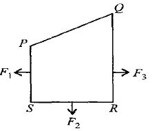
- 10A closed loop $PQRS$ carrying a current is placed in a uniform magnetic field. If the magnetic forces on segments $PS, SR$ and $RQ$ are $F_1, F_2$ and $F_3$ respectively and are in the plane of the paper and along the directions shown, the force on the segment $QP$ isView Solution