Two bulbs of $(40 \;W, 200\; V)$ and $(100\; W, 200 \;V)$. Then correct relation for their resistance
AIPMT 2000, Medium


Download our appand get started for free
Experience the future of education. Simply download our apps or reach out to us for more information. Let's shape the future of learning together!No signup needed.*
Similar Questions
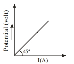
- 1The variation of applied potential and current flowing through a given wire is shown in figure. The length of wire is $31.4 \,cm$. The diameter of wire is measured as $2.4 \,cm$. The resistivity of the given wire is measured as $x \times 10^{-3} \,\Omega cm$. The value of $x$ is_______ [Take $\pi=3.14]$View Solution
- 2A battery of $e.m.f.$ $10\, V$ and internal resistance $0.5\, ohm$ is connected across a variable resistance $R$. The value of $R$ for which the power delivered in it is maximum is given by ......... $ohm$View Solution
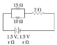
- 3In the given circuit, an ideal voltmeter connected across the $10\,\Omega $ resistance reads $2\, V$. The internal resistance $r$, of each cell is ................... $\Omega$View Solution
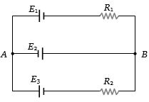
- 4In the circuit shown here, $E_1 = E_2 = E_3 = 2 V$ and $R_1 = R_2 = 4\,ohms$. The current flowing between points $A$ and $B$ through battery $E_2$ isView Solution
- 5View SolutionAn energy source will supply a constant current into the load if its internal resistance is
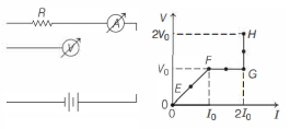
- 6In the circuit shown below (on the left) the resistance and the emf source are both variable. The graph of seven readings of the voltmeter and the ammeter ( $V$ and $I$, respectively) for different settings of resistance and the emf, taken at equal intervals of time $\Delta t$, are shown below (on the right) by the dots connected by the curve $E F G H$. Consider the internal resistance of the battery to be negligible and the voltmeter an ammeter to be ideal devices. (Take, $R_0 \equiv \frac{V_0}{I_0}$ ).View Solution
Then, the plot of the resistance as a function of time corresponding to the curve $E F G H$ is given by
- 7Two bulbs are working in parallel order. Bulb $A$ is brighter than bulb $B$. If ${R_A}$ and ${R_B}$ are their resistance respectively thenView Solution
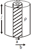
- 8Model a torch battery of length $l$ to be made up of a thin cylindrical bar of radius $'a'$ and a concentric thin cylindrical shell of radius ' $b$ ' fille in between with an electrolyte of resistivity $\rho$ (see figure). If the battery is connected to a resistance of value $R ,$ the maximum Joule heating in $R$ will take place forView Solution
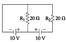
- 9In the given circuit the cells have zero internal resistance. The currents (in Amperes) passing through resistance $R_1$ and $R_2$ respectively, areView Solution
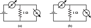
- 10A student uses the resistance of a known resistor $(1 \,\Omega)$ to calibrate a voltmeter and an ammeter using the circuits shown below. The student measures the ratio of the voltage to current to be $1 \times 10^3 \,\Omega$ in circuit $(a)$ and $0.999 \,\Omega$ in circuit $(b)$. From these measurements, the resistance (in $\Omega$ ) of the voltmeter and ammeter are found to be close toView Solution