- ACircuit 1 and circuit 2.
- B
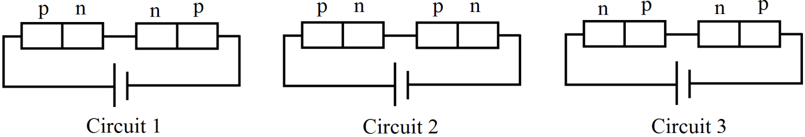
Circuit 2 and circuit 3.
- CCircuit 3 and circuit 1.
- DCircuit 1 only.


Explanation:
In circuit 1, one diode is forward biassed and the other diode is reverse biassed. The forward-biassed diode offers zero resistance (ideally) to the current flow, so it can be replaced by a short circuit. The voltage drop across the first diode will be zero. The second diode is reverse biassed, so it can be replaced by an open circuit; hence, the voltage drop across this diode will be maximum.
In circuit 2, both the diodes are forward biassed, so they can be replaced by short circuits; hence, the voltage drop across both of them will be minimum and equal.
In circuit 3, both the diodes are reverse biassed, so both can be replaced by open circuits; hence, the voltage drop across both of them will be maximum and equal.
Generate a complete, print-ready paper with questions like this in minutes — across 16+ boards, with answer keys.
The possible quantum number for 3d electron are
|
(a) n = 3, l = 1, |
(b) n = 3, l = 2, |
|
(c) n = 3, l = 1, |
(d) n = 3, l =0, |

A potentiometer has uniform potential gradient. The specific resistance of the material of the potentiometer wire is 10–7 ohm–meter and the current passing through it is 0.1 ampere; cross-section of the wire is 10–6 m2. The potential gradient along the potentiometer wire is
|
(a) |
(b) |
(c) |
(d) |
The variation of potential with distance R from a fixed point is as shown below. The electric field at R = 5 m is

|
(a) 2.5 volt/m |
(b) -2.5 volt/m |
(c) 2/5 volt/m |
(d) -2/5 volt/m |
The reason of seeing the Sun a little before the sunrise is
|
(a) Reflection of the light |
(b) Refraction of the light |
|
(c) Scattering of the light |
(d) Dispersion of the light |