Uniform electric field of magnitude $100$ $V/m$ in space is directed along the line $y = 3 + x$. Find the potential difference between point $A$ $ (3, 1)$ $\&$ $B$ $(1, 3)$.......$V$
Medium


Download our appand get started for free
Experience the future of education. Simply download our apps or reach out to us for more information. Let's shape the future of learning together!No signup needed.*
Similar Questions
- 1The equivalent capacitance of three capacitors of capacitance ${C_1},{C_2}$ and ${C_3}$ are connected in parallel is $12$ units and product ${C_1}.{C_2}.{C_3} = 48$. When the capacitors ${C_1}$ and ${C_2}$ are connected in parallel, the equivalent capacitance is $6$ units. Then the capacitance areView Solution
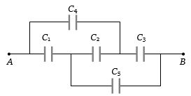
- 2In the given figure the capacitors ${C_1},{C_3},{C_4},{C_5}$ have a capacitance $4\,\mu F$ each if the capacitor $C_2$ has a capacitance $10\,F$, then effective capacitance between $A$ and $B$ will be.....$\mu F$View Solution
- 3A thin-walled, spherical conducting shell $S$ of radius $R$ is given charge $Q$. The same amount of charge is also placed at its centre $C. $ Which of the following statements are correct ?View Solution
- 4Two capacitors each of capacity $2\,\mu F$ are connected in parallel. This system is connected in series with a third capacitor of $12\,\mu F$ capacity. The equivalent capacity of the system will be......$\mu F$View Solution
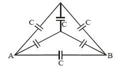
- 5Find net capacitance between $A$ and $B$View Solution
- 6The two thin coaxial rings, each of radius $'a'$ and having charges $+{Q}$ and $-{Q}$ respectively are separated by a distance of $'s'.$ The potential difference between the centres of the two rings is :View Solution
- 7A $10\,\mu F$ capacitor is charged to a potential difference of $1000\, V$. The terminals of the charged capacitor are disconnected from the power supply and connected to the terminals of an uncharged $6\, \mu F$ capacitor. What is the final potential difference across each capacitor?......$V$View Solution
- 8Potential difference between centre $\&$ the surface of sphere of radius $R$ and uniform volume charge density $\rho$ within it will be :View Solution
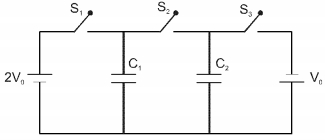
- 9In the circuit shown in the figure, there are two parallel plate capacitors each of capacitance $C$. The switch $S _1$ is pressed first to fully charge the capacitor $C_1$ and then released. The switch $S_2$ is then pressed to charge the capacitor $C _2$. After some time, $S _2$ is released and then $S _3$ is pressed. After some time.View Solution
$(A)$ the charge on the upper plate of $C _1$ is $2 CV _0$
$(B)$ the charge on the upper plate of $C _1$ is $CV _0$
$(C)$ the charge on the upper plate of $C _2$ is $0$
$(D)$ the charge on the upper plate of $C _2$ is $- CV _0$
- 10The work done in moving an electric charge $q$ in an electric field does not depend uponView Solution