When the power delivered by a $100\,volt$ battery is $40\,watts$ the equivalent resistance of the circuit is ........... $ohms$
AIIMS 2011, Easy
Download our app for free and get started
$P = \frac{{{V^2}}}{R} \Rightarrow \,R\, = \frac{{{V^2}}}{P}$

Download our appand get started for free
Experience the future of education. Simply download our apps or reach out to us for more information. Let's shape the future of learning together!No signup needed.*
Similar Questions
- 1View SolutionThe temperature at which thermal electric power of a thermo couple becomes zero is called
- 2On giving $220\,V$ to a resistor the power dissipated is $40\,W$ then value of resistance is ............... $\Omega$View Solution
- 3The circuit shown here is used to compare the $e.m.f.$ of two cells ${E_1}$ and ${E_2}({E_1} > {E_2})$. The null point is at $C$ when the galvanometer is connected to ${E_1}$. When the galvanometer is connected to ${E_2}$, the null point will beView Solution

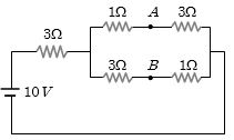
- 4A battery of $e.m.f.$ $10\, V$ is connected to resistance as shown in figure. The potential difference ${V_A} - {V_B}$ between the points $A$ and $B$ is .................... $V$View Solution
- 5View SolutionIn a metallic conductor, under the effect of applied electric field, the free electrons of the conductor
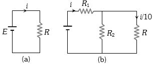
- 6Consider the circuits shown in the figure. Both the circuits are taking same current from battery but current through $R$ in the second circuit is $\frac{1}{{10}}$$^{th}$ of current through $R$ in the first circuit. If $R$ is $11$ $\Omega$, the value of $ R_1$ ................ $\Omega$View Solution
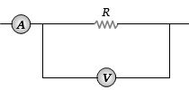
- 7The ammeter $A$ reads $2\, A$ and the voltmeter $V$ reads $20\, V$. the value of resistance $R$ is (Assuming finite resistance's of ammeter and voltmeter)View Solution
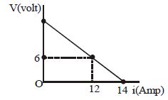
- 8$10\, Cells$, each of $emf$ $'E'$ and internal resistance $'r'$, are connected in series to a variable external resistance. Figure shows the variation of terminal potential difference of their combination with the current drawn from the combination.$Emf$ of each cell is ................ $V$View Solution
- 9$A$ battery consists of a variable number $n$ of identical cells having internal resistance connected in series. The terminals of the battery are short circuited and the current $I$ measured. Which one of the graph below shows the relationship between $I$ and $n$?View Solution
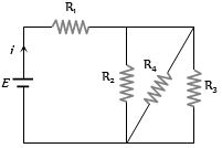
- 10In the circuit given $E = 6.0 \,V, R_1 = 100\, ohms, R_2 = R_3 = 50\, ohms, R_4 = 75\, ohms$. The equivalent resistance of the circuit, in $ohms$, isView Solution