Questions · Page 2 of 4

M.C.Q (1 Marks)

MCQ 511 Mark
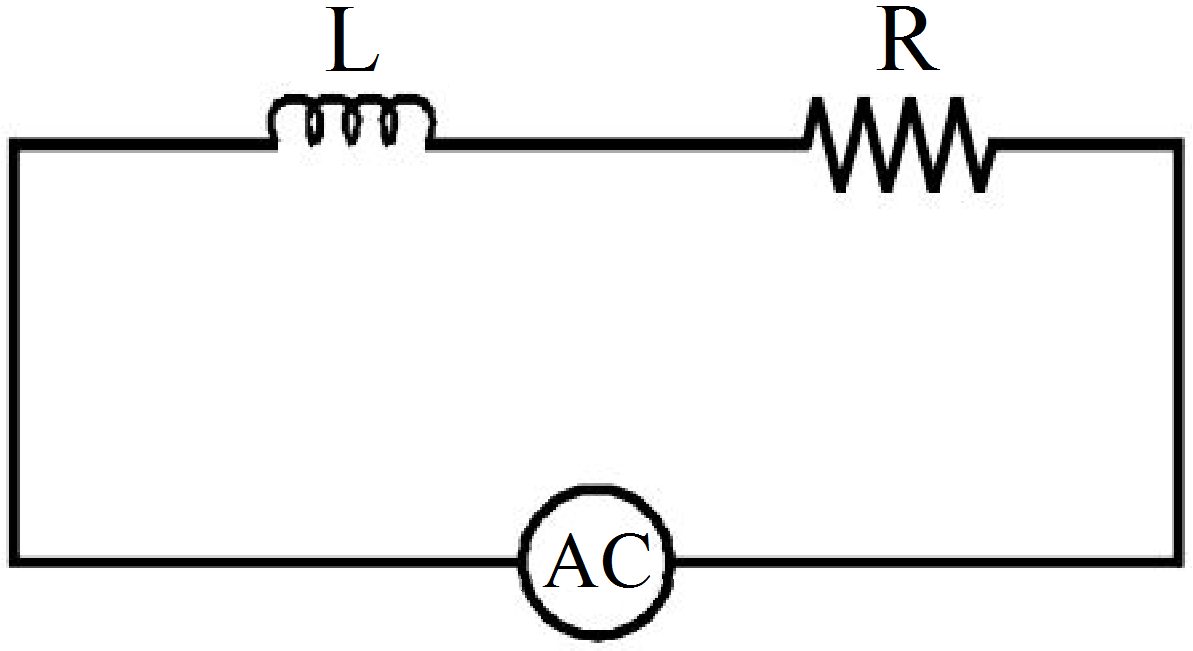
An inductor of reactance 1Ω and a resistor of 2Ω are connected in series to the terminals of a 6V (rms) a.c. source. The power dissipated in the circuit is:
  • A
    8W.
  • B
    12W.
  • C
    14.4W.
  • D
    18W.
Answer
  1. 14.4W.

Solution:

According to the problem, XL = 1Ω, R = 2Ω,

Erms = 6V, Pav = ?

Average power dissipated in the circuit

$\text{P}_\text{av}=\text{E}_\text{rms}\text{I}_\text{rms}\cos\phi \ .....(\text{i})$

$\text{I}_\text{rms}=\frac{\text{E}_\text{rms}}{\text{Z}}$

$\text{Z}=\sqrt{\text{R}^2+\text{X}^2_\text{L}}$

$=\sqrt{4+1}=\sqrt{5}$

$\text{I}_\text{rms}=\frac{6}{\sqrt{5}}\text{A}$

$\cos\phi=\frac{\text{R}}{\text{Z}}=\frac{2}{\sqrt{5}}$

$\text{P}_\text{av}=6\times\frac{6}{\sqrt{5}}\times\frac{2}{\sqrt{5}}\ \ [\text{from Eq. (i)]}$

$=\frac{72}{\sqrt{5}\sqrt{5}}=\frac{72}{5}=14.4\text{W}$​​​​​​​

View full question & answer
MCQ 521 Mark
The instantaneous voltage through a device of impedence $20\Omega$ is $\text{e}=80\sin100\pi\text{t}.$The effective value of the current is.
  • A
    3A
  • B
    2.828A
  • C
    1.732A
  • D
    4A
Answer
  1. 2.828A

Explantion:

Given equation, $\text{e}=80\sin100\pi\text{t}.(\text{i})$

Standard equation of instantaneous voltage given by E =

$\text{e}_\text{m}\sin(\omega\text{t})......(\text{i})$

Compare (i) and (ii), we get em​ = 80V

where em​ is the voltage amplitude.

Current amplitude $\text{I}_\text{m}=\frac{\text{e}_\text{m}}{\text{Z}}$ where Z = impedence

$=\frac{80}{20}=4\text{A}$

$\text{I}_\text{r.m.s}=\frac{4}{\sqrt{2}}=\frac{4\sqrt{2}}{2}=2\sqrt{2}=2.828\text{A}$

View full question & answer
MCQ 531 Mark
In a circuit L, C and R are connected in series with an alternating voltage source of frequency f. The current leads the voltage by 45°. The value of C is.
  • A
    $\frac{1}{2\pi\text{f}(2\pi\text{fL - R})}$
  • B
    $\frac{1}{2\pi\text{f}(2\pi\text{fL + R})}$
  • C
    $\frac{1}{\pi\text{f}(2\pi\text{fL - R})}$
  • D
    $\frac{1}{\pi\text{f}(2\pi\text{fL + R})}$
Answer
  1. $\frac{1}{2\pi\text{f}(2\pi\text{fL + R})}$

Explanation:

Here XC​ - XL ​= R

$\Rightarrow\frac{1}{2\pi\text{f}}=(\text{R}+2\pi\text{fL})$

$\Rightarrow\text{C}=\frac{1}{2\pi\text{f}(2\pi\text{fL + R})}$

View full question & answer
MCQ 541 Mark
The capacitive reactance of $50\mu\text{F}$ capacitance at a frequency of 2 × 10³Hz will be ____ $\Omega$
  • A
    $\frac{2}{\pi}$
  • B
    $\frac{3}{\pi}$
  • C
    $\frac{4}{\pi}$
  • D
    $\frac{5}{\pi}$
Answer
  1. $\frac{5}{\pi}$

Explanation:

Capacitive reactance $=\frac{1}{\omega\text{c}}$

$=\frac{1}{2\pi\text{fc}}$

$=\frac{1}{2\pi2\times10^3\times50\times10^{-6}}$

$=\frac{5}{\pi}\Omega$

View full question & answer
MCQ 551 Mark
The impedance of a series L - C - R circuit in an AC circuit is.
  • A
    $\sqrt{\text{R}+(\text{X}_\text{L}-\text{X}_\text{C})}$
  • B
    $\sqrt{\text{R}^2+(\text{X}_\text{L}^2-\text{X}_\text{C}^2)}$
  • C
    $\text{R}$
  • D
    $\text{None of these}$
Answer
  1. $\text{None of these}$

Explanation:

$\text{Z}=\sqrt{\text{R}^2+(\text{X}_\text{L}-\text{X}_\text{C})^2}$

View full question & answer
MCQ 561 Mark
Alternating current is one which changes in its:
  • A
    direction
  • B
    magnitude
  • C
    magnitude and direction both
  • D
    none
Answer
  1. magnitude and direction both

Explanation:

An alternating current (AC) is an electric current whose magnitude and direction vary, unlike direct current, whose direction remains constant.

The usual waveform of an AC power circuit is a sine wave, because this leads to the most efficient transmission of energy. The sine wave oscillates periodically between positive and negative direction.

View full question & answer
MCQ 571 Mark
A steady potential difference of 100V produces heat at a constant rate in a resistor. The alternating voltage which will produce half the heating effect in the same resister will be.
  • A
    100V
  • B
    50V
  • C
    70.7V
  • D
    141.4V
Answer
  1. 100V

Explanation:

The power supplied to the resistor by DC source $=\frac{\text{V}^2_\text{dc}}{\text{R}}$

Energy given by AC source $\int_{0}^{\text{T}}=\frac{\text{V}^2_0}{\text{R}}\text{dt}$

Hence, $\int_{0}^{\text{T}}=\frac{\text{V}^2_0\sin^2\omega\text{t}}{\text{R}}\text{dt}=\frac{1}{2}\times\frac{\text{V}^2_\text{dc}\text{T}}{\text{R}}$

$\Rightarrow\text{V}_0=\text{V}_\text{dc}=100\text{V}$

View full question & answer
MCQ 581 Mark
A 220V main supply is connected to a resistance of $100\text{k}\Omega$ The effective current is?
  • A
    $2.2\text{mA}$
  • B
    $2.2\sqrt{2\text{mA}}$
  • C
    $\frac{2.2}{\sqrt{2}}\text{mA}$
  • D
    $\text{None of these}$
Answer
  1. $2.2\text{mA}$

Explanation:

Effective current is the rms value. Here, 220V is the labelled value of AC which is also the rms value. Hence,

$\text{I}_\text{rms}=\frac{\text{E}_\text{rms}}{\text{R}}$

$\text{I}_\text{rms}=\frac{220}{100\times10^3}$

$\text{I}_\text{rms}=2.2{\text{mA}}$

View full question & answer
MCQ 591 Mark
An inductance and resistance are connected in series with an A.C circuit. In this circuit.
  • A
    the current and P.d. across the resistance lead P.d across the inductance by $\frac{\pi}{2}$
  • B
    the current and P.d across the resistance lags behind the P.d. across the inductance by angle $\frac{\pi}{2}$
  • C
    The current across resistance leads and the P.d across resistance lags behind the P.d across the inductance by $\frac{\pi}{2}$
  • D
    the current across resistance lags behind and the P.d across the resistance leads the P.d across the inductance by $\frac{\pi}{2}$
Answer
  1. the current and P.d across the resistance lags behind the P.d. across the inductance by angle $\frac{\pi}{2}$

Explanation:

This is very fundamental. If we apply separate voltages across resistance and inductor, then in resistance, current and voltage both are in same phase whereas in inductor, current across it lags p.d across it by $\frac{\pi}{2}.$
Now, when we apply voltage across inductor and resistance connencted in series then current through both of them will be same because of KCL. therefore voltage across resistor will be in same phase with current whereas voltage across inductor will lead the current across it by $\frac{\pi}{2}.$ therefore current and voltage across resistor lags voltage across inductor by $\frac{\pi}{2}$

View full question & answer
MCQ 601 Mark
A constant current of 2.8A exists in a resistor. The rms current is:
  • A
    2.8A.
  • B
    About 2A.
  • C
    1.4A.
  • D
    Undefined for a direct current.
Answer
  1. 2.8A.

Explanation:

A constant current exists in a resistor is rms current it is equal to 2.8Amp.

View full question & answer
MCQ 611 Mark
For watt-less power in an AC circuit the phase angle between the current and voltage is.
  • A
  • B
    90°
  • C
    45°
  • D
    Not possible
Answer
  1. 90°

Explanation:

Watt-less power in an AC circuit is basically power supposed to be generated by inductive and capacitive reactance and since they are not resistor they generate any heat, and these power wasted is called watt-less power and its phase angle is always 90o as it has only capacitor and inductor.

View full question & answer
MCQ 621 Mark
In an AC circuit, the impedance is 3​ times the reactance, then the phase angle is.
  • A
    60°
  • B
    30°
  • C
    zero
  • D
    none of these
Answer
  1. none of these

Explanation:

$\sin\phi=\frac{\text{X}}{\text{Z}}=\frac{1}{\sqrt{3}}$

$\therefore\phi=\sin^{-1}\Big(\frac{1}{\sqrt{3}}\Big)$

View full question & answer
MCQ 631 Mark
An AC source is rated 220V, 50Hz. The average voltage is calculated in a time interval of 0.01s, It:
  • A
    Must be zero.
  • B
    May be zero.
  • C
    Is never zero.
  • D
    Is $\Big(\frac{200}{\sqrt{2}}\Big)\text{V}.$
Answer
  1. May be zero.

Explanation:

  1. $\text{V}=\text{V}_0\sin\omega\text{t}$

$\omega=2\pi\text{f}=2\times3.14\times50$

$\omega=314$

$\text{V}_\text{avg}=\frac{\int\limits_0^{0.01}\text{V}\text{dt}}{\int\limits_0^{0.01}\text{dt}}$

$=\text{V}_0\Big(\frac{1\cos\omega\text{t}}{\omega}\Big)_0^{0.01}$

$=\frac{\text{V}_0}{\omega\times0.01}\big(1-\cos\omega(0.1)\big)$

$=\frac{\text{V}_0}{314\times0.01}\big(1-\cos(314\times0.01)\big)$

$=\frac{\text{V}_0}{3.14}\big(1-\cos(314)\big)$

$=\frac{\text{V}_0}{3.14}\big(1-\cos\pi\big)$

$=\frac{2\text{V}_0}{\pi}=140.127\text{volt}$

  1.  

if $\text{V}=\text{V}_0\cos\omega\text{t}$

$\text{V}_\text{avg}=\frac{\int\text{V d}\rho}{\int\text{dt}}=0$

View full question & answer
MCQ 641 Mark
The frequency of A.C mains in India is.
  • A
    30Hz
  • B
    50Hz
  • C
    60Hz
  • D
    120Hz
Answer
  1. 50Hz

Explanation:

In India, the AC mains supply is referred to as single-phase alternating current and corresponds to a voltage of 230 V at a frequency of 50Hz, similar to most European countries. Whereas in the USA, AC mains supply uses 60Hz.

View full question & answer
MCQ 651 Mark
Which of the following combinations should be selected for better tuning of an LCR circuit used for communication?
  • A
    R = 20Ω, L = 1.5H, C = 35μF.
  • B
    R = 25Ω, L = 2.5H, C = 45μF.
  • C
    R = 15Ω, L = 3.5H, C = 30μF.
  • D
    R = 25Ω, L = 1.5H, C = 45μF.
Answer
  1. R = 15Ω, L = 3.5 H, C = 30μF.

Solution:

Quality factor (Q) of an L-C-R circuit is given by, $\text{Q}=\frac{1}{\text{R}}\sqrt{\frac{\text{L}}{\text{C}}}$

Tuning of an L-C-R circuit depends on quality factor of the circuit. Tuning will be better when quality factor of the circuit is high.

As, quality factor (Q) of an L-C-R circuit is given by, $\text{Q}=\frac{1}{\text{R}}\sqrt{\frac{\text{L}}{\text{C}}}$

For Q to be high, R should be low, L should be high and C should be low, Therefore option (c) is most apporopriate.

View full question & answer
MCQ 661 Mark
In an ac circuit, the potential differences across an inductance and resistance joined in series are, respectively, 16V and 20V. The total potential difference across the circuit is.
  • A
    20V
  • B
    25.6V
  • C
    31.9V
  • D
    53.5V
Answer
  1. 25.6V

Explanation:

In phasor, $\text{V}_\text{R}=20\angle0;\text{V}_\text{L}=16\angle(-90)$

Total potential difference is $=\text{V}_\text{R}+\text{V}_\text{L}=25.6\angle(-38.66)$

Magnitude of total potential difference = 25.6V

View full question & answer
MCQ 671 Mark
The capacitor of an oscillatory circuit of negligible resistance is enclosed in a evacuated container. The frequency of the circuit is 150 kHZ and when the container is filled with a gas, the frequency changes by 100 HZ. The dielectric constant of the gas.
  • A
    2
  • B
    1.53
  • C
    1.0012
  • D
    3
Answer
  1. 1.0012

Explantion:

We know frequency is given by:

$\text{n}_1=\frac{1}{2\pi\sqrt{\text{LC}_1}}$

And

$\text{n}_2=\frac{1}{2\pi\sqrt{\text{LKC}_1}}$

Thus we get the ratio of frequencies as

$\frac{\text{n}_1}{\text{n}_2}=\frac{150000}{149900}=\sqrt{\text{k}}$

Solving the above equation we get, $\text{K}\approx1.0012$

View full question & answer
MCQ 681 Mark
A resistor and an inductor are connected to an ac supply of 120V and 50 Hz. The current in the circuit is 3A. If the power consumed in the circuit is 108W, then the resistance in the circuit is.
  • A
    $12\Omega$
  • B
    $40\Omega$
  • C
    $\sqrt{(52\times28)}\Omega$
  • D
    $360\Omega$
Answer
  1. $12\Omega$

Explanation:

Irms​ = currentincircuit = 3A

$\text{p}=108\text{W}=\text{I}_\text{ems}^2\text{R}=3^2\text{R}$

$\text{R}=\frac{108}{9}=12\Omega$

View full question & answer
MCQ 691 Mark
The phase difference between alternating emf and current in a purely capacitive circuit will be.
  • A
    $\text{zero}$
  • B
    $\pi$
  • C
    $-\frac{\pi}{2}$
  • D
    $\frac{\pi}{2}$
Answer
  1. $-\frac{\pi}{2}$

Explanation:

In a purely capacitive circuit, current leads the voltage by $-\frac{\pi}{2}$

View full question & answer
MCQ 701 Mark
What is the range of the characteristic impedance of a coaxial cable?
  • A
    $\text{Between }150\Omega \text{ to } 600\Omega$
  • B
    $\text{Between }50\Omega \text{ to } 70\Omega$
  • C
    $\text{Between }0\Omega \text{ to } 50\Omega$
  • D
    $\text{Between }100\Omega \text{ to } 150\Omega$
Answer
  1. $\text{Between }50\Omega \text{ to } 70\Omega$

Explanation:

Characteristic impedance of a coaxial cable is $\text{Between }50\Omega \text{ to } 70\Omega$

View full question & answer
MCQ 711 Mark
An inductor has a resistance R and inductance L. It is connected to an AC source of emf Ev​ and angular frequency ω; then the current Iv​ in the circuit is:
  • A
    $\frac{\text{E}_\text{v}}{\omega\text{L}}$
  • B
    $\frac{\text{E}_\text{v}}{\text{R}}$
  • C
    $\frac{\text{E}_\text{v}}{\sqrt{\text{R}^2+\omega^2\text{L}^2}}$
  • D
    $\sqrt{\Big(\frac{\text{E}_\text{v}}{\text{R}}\Big)^2+\Big(\frac{\text{E}_\text{v}}{\omega\text{L}}\Big)^2}$
Answer
  1. $\frac{\text{E}_\text{v}}{\sqrt{\text{R}^2+\omega^2\text{L}^2}}$

Explanation:

The impedance in R-L circuit is 

$\text{Z}=\sqrt{\text{R}^2+{\text{X}^2_\text{L}}}=\sqrt{\text{R}^2+{(\omega\text{L})^2}}$

The current $\text{I}_\text{V}=\frac{\text{E}_\text{V}}{\text{Z}}$

$\frac{\text{E}_\text{v}}{\sqrt{\text{R}^2+\omega^2\text{L}^2}}$

View full question & answer
MCQ 721 Mark
In R - L - C series circuit, the potential differences across each element is 20V. Now the value of the resistance alone is doubled, then P.D. across R, L and C respectively.
  • A
    20V, 10V, 10V
  • B
    20V, 20V, 20V
  • C
    20V, 40V, 40V
  • D
    10V, 20V, 20V
Answer
  1. 20V, 10V, 10V

Explanation:

Circuit is at resonance (VL = VC)

$\therefore$ circuit is purely resistance

Resistance is doubled, current in the circuit is half the initial value

$\therefore$ New current $\text{I′}=\frac{\text{I}}{2}$

$\therefore$ VR = 20V (equal to applied voltage earlier)

 VL = 10V

 VC = 10V

View full question & answer
MCQ 731 Mark
In an AC series circuit, the instantaneous current is zero when the instantaneous voltage is maximum. Connected to the source may be a:
  • A
    Pure inductor.
  • B
    Pure capacitor.
  • C
    Pure resistor.
  • D
    Combination of an inductor and a capacitor.
Answer
  1. Pure inductor.

  2. Pure capacitor.

  1. Combination of an inductor and a capacitor.

Explanation:

Instantaneous current is zero when the intantaneous voltage is maximum.

Mean resistance = 0.

View full question & answer
MCQ 741 Mark
If the frequency of an A.C is made 4 times of its initial value, the inductive reactance will.
  • A
    be 4 times
  • B
    be 2 times
  • C
    be half
  • D
    remain the same
Answer
  1. be 4 times

Explanation:

inductive reactance $=2\pi\text{fL}$

therefore when f is made 4 times, inductive reactance also becomes 4 times

View full question & answer
MCQ 751 Mark
In an AC circuit containing only capacitance, the current:
  • A
    leads the voltage by 180
  • B
    lags the voltage by 90
  • C
    leads the voltage by 90
  • D
    remains in phase with the voltage
Answer
  1. leads the voltage by 90

Explanation:

Current leads by 90°.

View full question & answer
MCQ 761 Mark
If the rms current in a 50Hz ac circuit is 5A, the value of the current $\frac{1}{300}$ seconds after its value becomes zero is,
  • A
    $5\sqrt{2}\text{A}$
  • B
    $5\sqrt{\frac{3}{2}}\text{A}$
  • C
    $\frac{5}{6}\text{A}$
  • D
    $\frac{5}{\sqrt{2}}\text{A}$
Answer
  1. $5\sqrt{\frac{3}{2}}\text{A}$

Solution:

Key concept: Equation for i and V: Alternating current or voltage varying as sine function can be written as

$\text{i}=\text{i}_0\ \sin\omega\text{t}=\text{i}_0\ \sin2\pi\text{v t}=\text{i}_0\sin\frac{2\pi}{\text{T}}\text{t}$

and $\text{V}=\text{V}_0\ \sin\omega\text{t}=\text{V}_0\ \sin2\pi\text{v t}=\text{V}_0\sin\frac{2\pi}{\text{T}}\text{t}$

where i and V are instantaneous values of current and voltage,

i0 and V0 are peak values of current and voltage

$\omega$ = Angular frequency in $\frac{\text{red}}{\text{sec}}$, v = Frequency in Hz and T = time period

Accoeding to the problem, f = 50Hz, Irms = 5A

$\text{t}=\frac{\text{I}}{300}\text{s}$

$\text{I}_0=\text{Peak value}=\sqrt{2}(\text{I}_\text{rms})=5\sqrt{2}$

$=5\sqrt{2}\text{A}$

From, $\text{I}=\text{I}_0\sin\omega\text{t}=5\sqrt{2}\sin2\pi\text{vt}=5\sqrt{2}\sin2\pi\times50\times\frac{1}{300}$

$=5\sqrt{2}\sin\frac{\pi}{3}=5\sqrt{2}\times\frac{\sqrt{3}}{2}=5\sqrt{\frac{3}{2}}\text{A}$

View full question & answer
MCQ 771 Mark
In a series LCR circuit, resonance occurring at 105Hz. At that time, the potential difference across the 100 resistance is 40V while the potential difference across the pure inductor is 30v. The inductance L of the inductor is equal to.
  • A
    2.0 × 10⁻⁴
  • B
    3.0 × 10⁻⁴
  • C
    1.2 × 10⁻⁴
  • D
    2.4 × 10⁻⁴
Answer
  1. 1.2 × 10⁻⁴

Explanation:

In a series LCR circuit, resonance occurring at 105Hz. At that time, the potential difference across the 100 resistance is 40V while the potential difference

across the pure inductor is 30V. The inductance L of the inductor is equal to

Current(i) $=\frac{\text{V}_\text{r}}{\text{R}}=\frac{100}{40}=2.5\text{A}$

the inductor value is VL ​= i × (wL)

$\text{L}=\frac{30}{2.5\times2\times\pi1\times105}=1.2\times10^{-4}\text{H}$

View full question & answer
MCQ 781 Mark
A 5cm long solenoid having 10 ohm resistance and 5mH inductance is joined to a 10V battery. At steady state, the current through the solenoid (in ampere) will be.
  • A
    5
  • B
    2
  • C
    1
  • D
    zero
Answer
  1. 1

Explanation:

At steady state inductor behave like short circuit.

$\text{i}=\frac{\text{v}}{\text{r}}=\frac{10}{10}=1\text{A}$

View full question & answer
MCQ 791 Mark
The magnetic field energy in an inductor changes from maximum value to minimum value in 5.0ms when connected to an AC source. The frequency of the source:
  • A
    20Hz.
  • B
    50Hz.
  • C
    200Hz.
  • D
    500Hz.
Answer
  1. 50Hz.

Explanation:

Frequency of the source is remain constant = 50Hz.

View full question & answer
MCQ 801 Mark
Inductive reactance of a coil is expressed in.
  • A
    Amphere
  • B
    Ohm
  • C
    Volt
  • D
    Weber
Answer
  1. Ohm

Explanation:

Inductive reactance or capacitive reactance are the impedance of an AC circuit which has the units of ohms.

View full question & answer
MCQ 811 Mark
An LCR series circuit with $100\Omega$ resistance is connected to an ac source of 200V and of frequency of $\frac{300 \text{rad}}{\text{s}}$. When only the capacitance is removed, the current lags behind the voltage by 600. When only the inductance is removed, the current leads the voltage by 60° the current through the circuit is:
  • A
    1 A
  • B
    2 A
  • C
    3 A
  • D
    4 A
Answer
  1. 2 A

Explanation:

Since current lead and lag are same So, circuit is in resonance, so, circuit is purely resistive circuit.

So, $\text{i}=\frac{\text{V}}{\text{R}}$

$=\frac{200}{100}$

$=2\text{A}$

View full question & answer
MCQ 821 Mark
A capacitor acts as an infinite resistance for.
  • A
    DC
  • B
    AC
  • C
    DC as well as AC
  • D
    neither AC nor DC
Answer
  1. DC

Explanation:

Capacitors contain at least two electrical conductors separated by a dielectric/ insulator and is used to store energy electrostatically between the conductors. It acts like an open circuit and hence acts like an infinite resistance for DC currents.

View full question & answer
MCQ 831 Mark
An inductor coil of some resistance is connected to an AC source. Which of the following quantities have zero average value over a cycle?
  • A
    Current.
  • B
    Induced emf in the inductor.
  • C
    Joule heat.
  • D
    Magnetic energy stored in the inductor.
Answer
  1. Current.
  2. Induced emf in the inductor.

Explanation:

$\text{I}=\text{I}_0\sin\omega\text{t}$

Average value of current over a cycle = 0

$\text{V}=\text{V}_0\cos\omega\text{t}$

$=\text{V}_0\sin\bigg(\omega\text{t}+{\frac{\pi}{2}}\bigg)$

Average value of induced emf in inductor over a cycle = 0.

View full question & answer
MCQ 841 Mark
In a series L - C - R circuit, current in the circuit is 11A when the applied voltage is 220V. Voltage across the capacitor is 200V. If value of resistor $20\Omega$ then the voltage across the unknown inductor is.
  • A
    Zero
  • B
    200V
  • C
    20V
  • D
    None of these
Answer
  1. 200V

Explanation:

The given LCR circuit is in resonance. Inductive reactance magnitude XL​ increases as frequency increases while capacitive reactance magnitude XC​ decreases with the increase in frequency.

At one particular frequency, these two reactances are equal in magnitude but opposite in sign; that frequency is called the resonant frequency fO​ for the given circuit. Hence, at resonance:

XL ​= XC​

So the voltage across rthe unknown inductor is 200V as same as the voltage across the capacitor.

View full question & answer
MCQ 851 Mark
An LCR circuit has L = 10 mH, $\text{R}=3\Omega$ and $\text{C}=1\mu\text{ F}$ connected in series to a source of $15\cos\omega\text{t}$ volt. The current amplitude at a frequency that is 10% lower than the resonant frequency is:
  • A
    0.5A
  • B
    0.7A
  • C
    0.9A
  • D
    1.1A
Answer
  1. 0.7A

Explanation:

Resonant frequency, $\text{w}_\text{o}=\frac{1}{\sqrt{\text{LC}}}=\frac{1}{\sqrt{(10\times10^{-3})(10^{-6})}}=\frac{10^4\text{rad}}{\text{s}}$

New frequency $\omega=(0.9)\omega_\text{o}=9\times\frac{10^3\text{rad}}{\text{s}}$

We have new $\text{X}_\text{L}=\omega\text{L}=9\times10^3\times10\times10^{-3}=90\Omega\text{ and}\text{ X}_\text{C}=\frac{1}{\omega\text{C}}=111.11\text{ohm.}$

Thus we calculate new Z as

$\sqrt{3^2+[90-111.11]^2}$

$=21.32\Omega$

Current amplitude $=\frac{\text{V}_\text{o}}{\text{Z}}=\frac{15}{21.32}=0.7\text{A}$

View full question & answer
MCQ 861 Mark
At low frequency a condenser offers:
  • A
    high impedance
  • B
    low impedance
  • C
    zero impedance
  • D
    impedance of condenser is independent of frequency
Answer
  1. high impedance

Explanation

$\text{Z}=\frac{1}{\text{WC}}$

$\text{W}\downarrow\text{Z}\uparrow$

View full question & answer
MCQ 871 Mark
An A.C. circuit containing only capacitance, the current:
  • A
    Lags the voltage by 90°
  • B
    Leads the voltage by 90°
  • C
    Remains in phase with voltage
  • D
    Lags the voltage by 180°
Answer
  1. Leads the voltage by 90°

Explanation:

In an a.c. circuit containing resistance onIy voltage & current remain in the same phase. If circuit contains inductance only, voltage remains ahead of current by phase difference of 90°. If circuit contains capacitance only, current remains ahead of voltage by a phase difference of 90°.

View full question & answer
MCQ 881 Mark
In an alternating current circuit consisting of elements in series, the current increases on increasing the frequency of supply. Which of the following elements are likely to constitute the circuit?
  • A
    Only resistor.
  • B
    Resistor and an inductor.
  • C
    Resistor and a capacitor.
  • D
    Only a capacitor.
Answer
  1. Resistor and a capacitor.
  2. Only a capacitor.

Solution:

This is the similar problem as we discussed above. In this problem, the current increases on increasing the frequency of supply. Hence, the reactance of the circuit must be decreased as increase in frequency. So, one element that must be connected is capacitor. We can also connect a resistor in series.

For a capacitive circuit,

$\text{X}_\text{C}=\frac{1}{\omega\text{C}}=\frac{1}{2\pi\text{fC}}$

When frequency increases, XC decreases. Hence current in the circuit increases.

Importance point: Resistive, Capacitive Circuit (RC-Circuit)

VR = iR,

VC = iXC,

VR = iR

  1. Applied voltage: $\text{V}=\sqrt{\text{V}^2_\text{R}+\text{V}^2_\text{C}}$

  2. Impedance: $\text{Z}=\sqrt{\text{R}^2+\text{X}^2_\text{C}}=\sqrt{\text{R}^2+\Big(\frac{1}{\omega\text{C}}\Big)^2}$

  3. Current: $\text{i}=\text{i}_0\sin(\omega\text{t}+\phi)$

  4. Peak current: $\text{i}_0=\frac{\text{V}_0}{\text{Z}}=\frac{\text{V}_0}{\sqrt{\text{R}^2+\text{X}^2_\text{C}}}=\frac{\text{V}_0}{\sqrt{\text{R}^2+\frac{1}{4\pi^2\text{v}^2\text{C}^2}}}$

  5. Phase difference: $\phi=\tan^{-1}\frac{\text{X}_\text{C}}{\text{R}}=\tan^{-1}\frac{1}{\omega\text{CR}}$

  6. Power factor: $\cos\phi=\frac{\text{R}}{\sqrt{\text{R}^2+\text{X}^2_\text{C}}}$

  7. Leading quantity: Current.

View full question & answer
MCQ 891 Mark
What is the value of inductance L for which the current is a maximum in a series LCR circuit with $\text{C}=10\mu\text{F}$ and $\omega=1000_\text{s}^{-1}$?
  • A
    10mH
  • B
    100mH
  • C
    1mH
  • D
    cannot be calculated unless R is known
Answer
  1. 100mH
View full question & answer
MCQ 901 Mark
In an oscillating system, a restoring force is a must. In an L-C circuit, the restoring force is provided by a/ an.
  • A
    inductor
  • B
    capacitor
  • C
    resistor
  • D
    both A and B
Answer
  1. inductor.
View full question & answer
MCQ 911 Mark
A resistor and a capacitor are in series across a 20V ac source. Circuit impedance is $4.33\text{k}\Omega$ Current flow in the circuit is.
  • A
    9.2mA
  • B
    92mA
  • C
    4.6mA
  • D
    460mA
Answer
  1. 4.6mA

Explanation:

Voltage of the source V = 20 volts

$\text{Z}=4.33\text{k}\Omega=4.33\times10^3\Omega$

Thus current in the circuit $\text{I}=\frac{\text{V}}{\text{Z}}$

$\therefore\text{I}=\frac{20}{4.33\times10^3}=4.6\times10^{-3}\text{A}$

$\Rightarrow\text{I}=4.6\text{mA}$

View full question & answer
MCQ 921 Mark
A mixer of $100\Omega$ resistance is connected to an A.C. source of 200V and 50 cycles/ sec. The value of average potential difference across the mixer will be:
  • A
    308 V
  • B
    264 V
  • C
    220 V
  • D
    zero
Answer
  1. zero

Explanation:

We need to find the average potential difference across the mixer. Here by average we mean average over a long period of time. As we know in one complete cycle, average voltage across the mixer is zero. (In one complete cycle current changes the direction and net voltage across a resistor is zero). 
So when in one complete cycle voltage drop across the resistor is zero, then the average voltage drop across the resistor (mixer) is zero.

View full question & answer
MCQ 931 Mark
If we increase the driving frequency in a circuit with a purely resistive load, then amplitude VR​.
  • A
    remain in the same
  • B
    increase
  • C
    decrease
  • D
    none
Answer
  1. remain in the same

Explanation:

We know that VR​ does not depend on driving frequency in a purely resistive circuit. So, If we increase the driving frequency in a circuit with a purely resistive load, then amplitude remain in the same.

View full question & answer
MCQ 941 Mark
The square root of the product of inductance and capacitance has dimensions of.
  • A
    length
  • B
    mass
  • C
    time
  • D
    dimensionless
Answer
  1. time

Explanation:

$\text{f}=\frac{1}{\sqrt{\text{LC}}}$

$\text{or}{\sqrt{\text{LC}}}=\text{T}$

View full question & answer
MCQ 951 Mark
An inductor, a resistor and a capacitor are joined in series with an AC source. As the frequency of the source is slightly increased from a very low value, the reactance.
  • A
    of the inductor increases
  • B
    of the resistor increases
  • C
    of the capacitor increases
  • D
    of the circuit increases
Answer
  1. of the inductor increases
View full question & answer
MCQ 961 Mark
For an LCR circuit, the power transferred from the driving source to the driven oscillator is $\text{P}=\text{FZ}\cos\phi$.
  • A
    Here, the power factor $\cos\phi\geq0,\text{P}\geq0$.
  • B
    The driving force can give no energy to the oscillator (P = 0) in some cases.
  • C
    The driving force cannot syphon out (P < 0) the energy out of oscillator.
  • D
    The driving force can take away energy out of the oscillator.
Answer
  1. Here, the power factor $\cos\phi\geq0,\text{P}\geq0$.
  2. The driving force can give no energy to the oscillator (P = 0) in some cases.
  3. The driving force cannot syphon out (P < 0) the energy out of oscillator.

Solution:

Key Concept: Power Factor.

  1. It may be defined as cosine of the angle of lag of lead (i.e., $\cos\phi$).
  2. It is also defined as the radio of resistance and impedange $\Big(\text{i.e.,} \frac{\text{R}}{\text{Z}}\Big)$.
  3. $\text{The radio}=\frac{\text{True power}}{\text{Apparent power}}=\frac{\text{W}}{\text{VA}}=\frac{\text{kW}}{\text{kVA}}=\cos\phi$

In the given problem power transferred,

$\text{P}=\text{I}^2\text{Z}\cos\phi$

where I is the current, Z = Impedance and $\cos\phi$ is power factor

  1. As power factor, $\cos\phi=\frac{\text{R}}{\text{Z}}$

where R > 0 and Z > 0

$\Rightarrow\ \cos\phi>0\Rightarrow\ \text{P}>0$

  1. When $\phi=\frac{\pi}{2}$ (in case of L of C), P = 0.
  2. From (a), it is clear that P < 0 is not possible.
View full question & answer
MCQ 971 Mark
The equation of an alternating voltage is E = 220 E = 220.Then the impedance of the circuit is:
  • A
    10 ohm
  • B
    22 ohm
  • C
    11 ohm
  • D
    17 ohm
Answer
  1. 22 ohm

Explanation:

Our experts are building a solution for this.

View full question & answer
MCQ 981 Mark
A series AC circuit has a resistance of $4\Omega$ and a reactance of $3\Omega$. The impedance of the circuit is.
  • A
    $5\Omega$
  • B
    $7\Omega$
  • C
    $\frac{12}{7\Omega}$
  • D
    $\frac{7}{12\Omega}$
Answer
  1. $5\Omega$

Explanation:

Impedance(Z) $=\sqrt{\text{R}^2+\text{X}^2}$

where, R = resistance

X = reactance

Given $\text{R}=4\Omega\text{ and }\text{X}=3\Omega$

Substitute values back in equation

$\text{Z}=\sqrt{4^2+3^2}$

$\text{Z}=5\Omega$

View full question & answer
MCQ 991 Mark
The AC voltage across a resistance can be measured using:
  • A
    A potentiometer.
  • B
    A hot-wire voltmeter.
  • C
    A moving-coil galvanometer.
  • D
    A moving-magnet galvanometer.
Answer
  1. A hot-wire voltmeter.

Explanation:

The AC voltae across a resustance can be measured using a hot-wore volmeter.

View full question & answer
MCQ 1001 Mark
In non-resonant circuit, what will be the nature of the circuit for frequencies higher than the resonant frequency?
  • A
    Resistive
  • B
    Capacitive
  • C
    Inductive
  • D
    None of these
Answer
  1. Inductive

Explanation:

At resonant frequency

$\text{X}_\text{L}=\text{X}_\text{C}=\Big(\omega\text{L}=\frac{1}{\omega\text{C}}\Big)$

At frequencies higher than resonance frequencies

$\text{X}_\text{L}>\text{X}_\text{C}$

i.e., behaviour is inductive.

View full question & answer