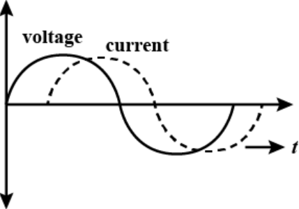
- Zero average current.
- Voltage and current possibly differing in phase $\phi$ such that $\Big|\phi\Big|<\frac{\pi}{2}$.
Solution:
Alternation currents are used for household supplies, which are having zero average value over a cycle.
The line is having some resistance, so power factor $\cos\phi=\frac{\text{R}}{\text{Z}}\neq0$
So, $\phi\neq\frac{\pi}{2}\Rightarrow\ \phi<\frac{2}{\pi}$
i.e., phase lies between 0 and $\frac{\pi}{2}$.
Important point: The average value of alternating quantity for one complete cycle is zero.
The average value of ac over half cycle $\Big(\text{t}=0\text{ to }\frac{\text{T}}{2}\Big)$
$\text{i}_\text{av}=\frac{\int_0^{\frac{\text{T}}{2}}\text{idt}}{\int_0^{\frac{\text{T}}{2}}\text{dt}}=0.637\text{i}_0=63.7\% \ \text{of i}_0$
Similarly $\text{V}_\text{av}=\frac{2\text{V}_0}{\pi}=0.637\text{V}_0=63.7\%\ \text{of V}_0.$