Question 13 Marks
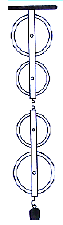
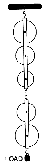
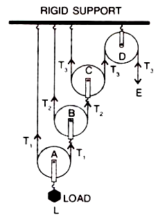
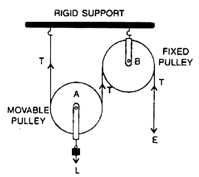
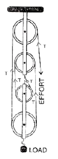
In following figure , shows a block and tackle system of pulleys used to lift a load.
(a) How many strands of tackle are supporting the load?
(b) Draw arrows to represent tension in each strand.
(c) What is the mechanical advantage of the system?
(d) When load is pulled up be a distance 1 m, how far does the effort end move?
(a) How many strands of tackle are supporting the load?
(b) Draw arrows to represent tension in each strand.
(c) What is the mechanical advantage of the system?
(d) When load is pulled up be a distance 1 m, how far does the effort end move?
Answer
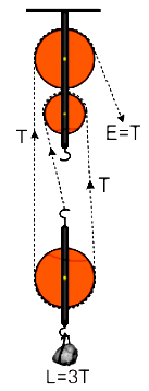
View full question & answer→(a) There are 4 strands of tackle supporting the load.
(b)
(c) The mechanical advantage of the system
$
MA =\frac{\text { Load }}{\text { effort }}=\frac{4 T}{T}=4
$
(d) When load is pulled up by a distance $1 m$, the effort end will move by a distance $=1 \times 4=4 m$.
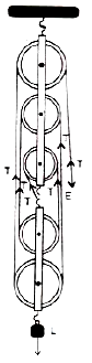
(b)
(c) The mechanical advantage of the system
$
MA =\frac{\text { Load }}{\text { effort }}=\frac{4 T}{T}=4
$
(d) When load is pulled up by a distance $1 m$, the effort end will move by a distance $=1 \times 4=4 m$.