Question 515 Marks
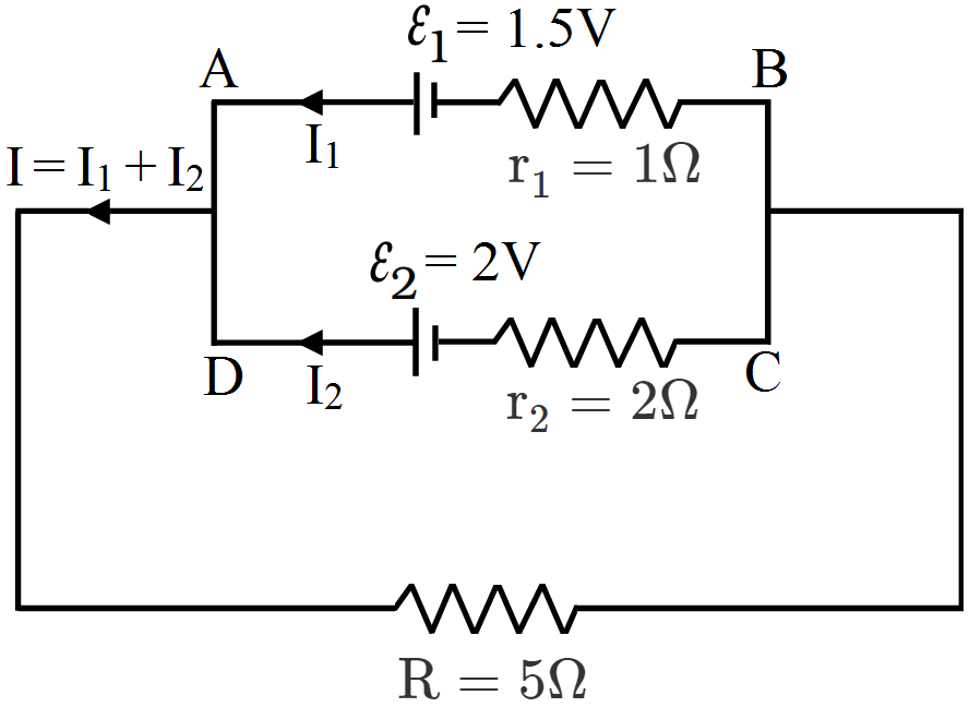
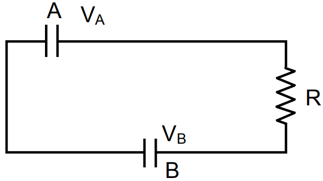
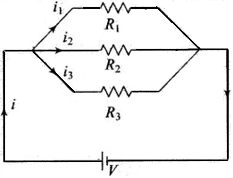
Two cells of emf 1.5V and 2V and internal resistance $1\Omega$ and $2\Omega$ respectively are connected in parallel to pass a current in the same direction through an external resistance of $5\Omega.$
- Draw the circuit diagram.
- Using Kirchhoff’s laws, calculate the current through each branch of the circuit and potential difference across $5\Omega$ resistor.
Answer
- The circuit is shown in figure.
- Suppose $I_1$ are $I_2$ current drawn from cells $\varepsilon_1$ and $\varepsilon_2$ respectively, then
According to Kirchhoff’s junction law, current in $\text{R}=5\Omega,\text{I}=\text{I}_1+\text{I}_2.$
Applying Kirchhoff’s second law to mesh ABFEA
$1\times\text{I}_1+1.5-5(\text{I}_1+\text{I}_2)=0$
$\Rightarrow\text{I}_1+5\text{I}_2=1.5\dots\text{(i)}$
Applying Kirchhoff’s second law to mesh CDEFC
$-2\text{I}_2+2-5(\text{I}_1+\text{I}_2=0$
$\Rightarrow\text{5I}_1+7\text{I}_2=2\dots\text{(ii)}$
Solving equation (i) and (ii), we get
$\text{I}_1=\frac{1}{34}\text{A},\text{I}_2=\frac{9}{34}\text{A}$
$\text{I}=\text{I}_1+\text{I}_2=\frac{1}{34}+\frac{9}{34}=\frac{10}{34}$
Potential difference avross $\text{R}=5\Omega$ resistor
$(\text{I}_1+\text{I}_2)\text{R}=\frac{10}{34}\times5=\frac{25}{17}\text{Volt}$ View full question & answer→Question 525 Marks
Two conductors are made of the same material and have the same length. Conductor A is a solid wire of diameter 1mm. Conductor B is a hollow tube of outer diameter 2mm and inner diameter 1mm. Find the ratio of resistance $R_A$ to $R_B.$
AnswerResistance of a wire is given by, $\text{R}=\rho\Big(\frac{\text{l}}{\text{A}}\Big)$, where l is length of the conductor and A is the area of the cross-section & $\rho$ is a constant.
Resistance of first conductor, $\text{R}_\text{A}=\rho\Big[\frac{\text{l}}{\pi}(10^{-3}\times0.5)^2\Big]$
Resistance of second conductor, $\text{R}_\text{B}=\rho\Big[\frac{\text{l}}{\pi}\{(10^{-3})^2-(0.5\times10^{-3})^2\}\Big]$
Ratio, $\frac{\text{R}_\text{A}}{\text{R}_\text{B}}=\frac{\Big[\pi\{(10^{-3})^2-(0.5\times10^{-3})^2\Big]}{(10^{-3}\times0.5)^2}$
$\Rightarrow\ \frac{\text{R}_\text{A}}{\text{R}_\text{B}}=3:1.$
View full question & answer→Question 535 Marks
Explain with the help of a circuit diagram how the value of unknown resistance can be determined using a Wheatstone Bridge. Give the formula used.
AnswerDetermination of Unknown resistance by Wheatstone Bridge. The circuit diagram is completed as shown in fig. P and Q are each $10\Omega$ resistance, RB is a resistance box and X is unknown resistance to be measured. B is battery with key $K_1$ (in series, G is galvanometer with key $K_2$ in series.)
The battery key $K_1$ is pressed first and smallest resistance in RB is introduced by pressing galvanometer by $K_2$, the deflection in galvanometer is noted. Now resistance in RB is introduced, by pressing galvanometer key the deflection should be on other side. This is the main precaution before starting the experiment. Now suitable value of resistance in RB is chosen so that on pressing the galvanometer key, there is no deflection in galvanometer. This resistance R is noted. Now formula used is, $\frac{\text{P}}{\text{Q}}=\frac{\text{R}}{\text{X}}$ ⇒ Unknown resistance. $\text{X}=\frac{\text{Q}}{\text{P}}\text{R}$ can be calculated. View full question & answer→Question 545 Marks
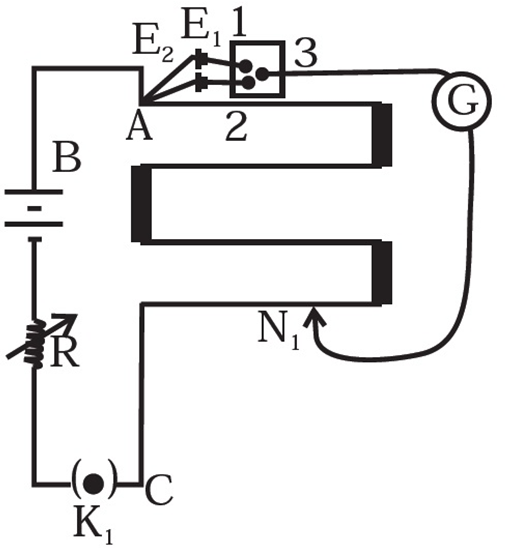
Figure shows a potentiometer with a cell of 2.0V and internal resistance of $0.40\Omega$ maintaining a potential drop across the resistor wire AB. A standard cell which maintains a constant emf of 1.02V (for very moderate currents upto a few mA) gives a balance point at 67.3cm length of the wire. To ensure very low currents drawn from the standard cell, a very high resistance of $600\text{k}\Omega$ is put in series with it, which is shorted close to the balance point. The standard cell is then replaced by a cell of unknown emf and the balance point found similarly, turns out to be at 82.3cm length of the wire.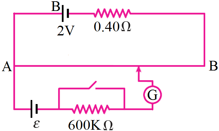
- What is the value of $\varepsilon?$
- What purpose does the high resistance of $600\text{k}\Omega$ have?
- Is the balance point affected by this high resistance?
- Is the balance point affected by the internal resistance of the driver cell?
- Would the method work in the above situation if the driver cell of the potentiometer had an emf of 1.0V instead of 2.0V?
- Would the circuit work well for determining extremely small emf, say of the order of few mV (such as the typical emf of a thermo couple)? If not, how would you modify the circuit?
Answer
- For same potential gradient of potentiometer wire, the formula for comparison of emfs of cells is,
$\frac{\varepsilon_2}{\varepsilon_1}=\frac{\text{l}_2}{\text{l}_1}\Rightarrow\frac{\varepsilon}{\varepsilon_\text{s}}=\frac{\text{l}}{\text{l}_\text{s}}$
$\varepsilon=\frac{\text{l}}{\text{l}_\text{s}}\varepsilon_\text{s}$
$\varepsilon_\text{s}=$ emf of standard cell = 1.02V
$I_s =$ balancing with length standard cell = 67.3cm
$l =$ balancing length with cell of unknown emf = 82.3cm
$\therefore$ Unknown emf $\varepsilon=\frac{(82.3\text{cm})}{(67.3\text{cm})}\times1.02\text{V}=1.25\text{V}$
- The purpose of high resistance is to reduce the current through the galvanometer. When jockey is far from the balance point, this saves the standard cell from being damaged.
- The balance point is not affected by the presence of high resistance because in balanced-position there is no current in cell-circuit (secondary circuit).
- No, the balance point is not affected by the internal resistance of driver cell, because we have already set the constant potential gradient of wire.
- No, since for the working of potentiometer the emf of driver cell must be greater than emf of secondary circuit.
- No, the circuit will have to be modified by putting variable resistance (R) in series with the driver cell the value of R is so adjusted that potential drop across wire is slightly greater than emf of secondary cell, so that the balance point may be obtained at a longer length. This will reduce the error and increase the accuracy of measurement.
View full question & answer→Question 555 Marks
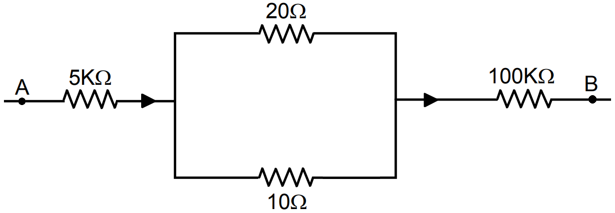
Figure. shows a part of a circuit. If a current of 12mA exists in the $5\text{k}\Omega$ resistor, find the currents in the other three resistors. What is the potential difference between the points A and B?
Answer
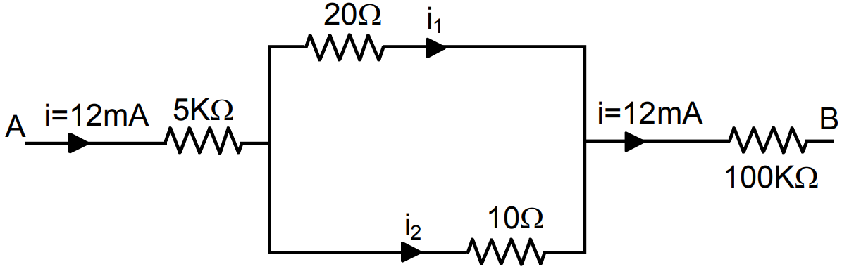
$\text{i}_1\times20=\text{i}_2\times10$
$\Rightarrow\frac{\text{i}_1}{\text{i}_2}=\frac{10}{20}=\frac{1}{2}$
$i_1 = 4mA, i_2 = 8mA$
Current in $20\text{K}\Omega$ resistor = 4mA
Current in $10\text{K}\Omega$ resistor = 8mA
Current in $100\text{K}\Omega$ resistor = 12mA
$\text{V}=\text{V}_1+\text{V}_2+\text{V}_3$
$=5\text{K}\Omega\times12\text{mA}+10\text{K}\Omega\times8\text{mA}\\+100\text{K}\Omega\times12\text{mA}$
$=60+80+1200=1340\text{ volts}.$ View full question & answer→Question 565 Marks
First a set of n equal resistors of R each are connected in series to a battery of emf E and internal resistance R. A current I is observed to flow. Then the n resistors are connected in parallel to the same battery. It is observed that the current is increased 10 times. What is 'n'?
AnswerKey concept: The equivalent resistance of series combination is in series with the internal resistance R of battery and in parallel combination of resistors, the equivalent resistance of parallel combination is also in series with the internal resistance of battery.
In series combination of resistors, current I is given by $\text{I}=\frac{\text{E}}{\text{R}+\text{nR}}$
whereas in parallel combination current 10I is given by
$\text{I}=\frac{\text{E}}{\text{R}+\frac{\text{R}}{\text{n}}}10\text{I}$
Now, according to problem,
$\frac{1+\text{n}}{1+\frac{\text{I}}{\text{n}}}\Rightarrow\ 10=\bigg(\frac{\text{l}+\text{n}}{\text{n}+\text{l}}\bigg)\text{n}$
$\Rightarrow\ \text{n}=10$
View full question & answer→Question 575 Marks
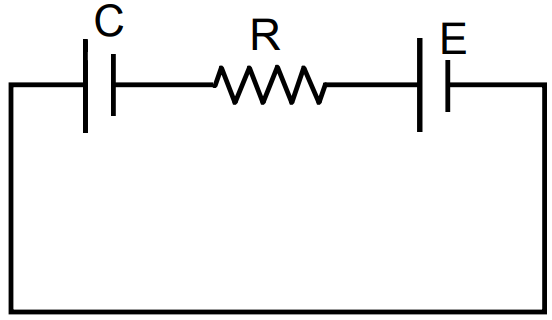
A capacitance C, a resistance R and an emf $\in$ are connected in series at t = 0. What is the maximum value of (a) the potential difference across the resistor (b) the current in the circuit (c) the potential difference across the capacitor (d) the energy stored in the capacitor (e) the power delivered by the battery and (f) the power converted into heat?
Answer
- Potential difference = E across resistor
- Current in the circuit $=\frac{\text{E}}{\text{R}}$
- Pd. Across capacitor $=\frac{\text{E}}{\text{R}}$
- Energy stored in capacitor $=\frac{1}{2}\text{CE}^2$
- Power delivered by battery $=\text{E}\times\text{I}=\text{E}\times\frac{\text{E}}{\text{R}}=\frac{\text{E}^2}{\text{R}}$
- Power converted to heat $=\frac{\text{E}^2}{\text{R}}$
View full question & answer→Question 585 Marks
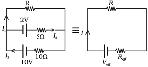
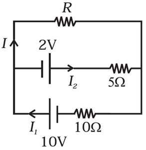
Two cells of voltage 10V and 2V and internal resistances 10Ω and 5Ω respectively, are connected in parallel with the positive end of 10V battery connected to negative pole of 2V battery (Fig). Find the effective voltage and effective resistance of the combination.
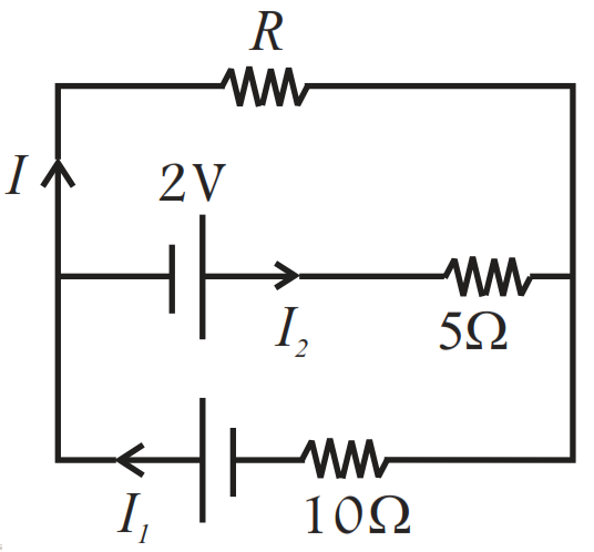
AnswerApplying Kirchhoff’s junction rule,
we have $I_1 = I + I_2$ Kirchhoff’s loop rule gives: $10 = IR + 10I_1 ....(i)$
$2 = 5I_2 - RI = 5 (I_1 - I) - RI 4 = 10I_1 - 10I - 2RI ..... (ii)$
Subtracting $…(i) & …(ii),$ we have $6 = 3RI + 10I$
or, $2=\text{I}\Big(\text{R}_\text{eff}=\frac{10}{3}\Big)$ 2
$= (R + R_{eff})I Comparing with V_{eff} = (R + R_{eff})I and V_{eff}= 2\ V \text{R}_\text{eff}=\frac{10}{3}\Omega.$
View full question & answer→Question 595 Marks
- Calculate the equivalent resistance of the given electrical network between points A and B.
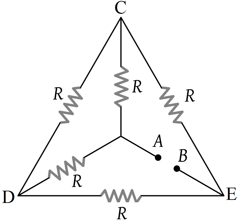
- Also calculate the current through CD and ACB if a 10V dc source is connected between points A and B and the value of $\text{R}=2\Omega.$
Answer
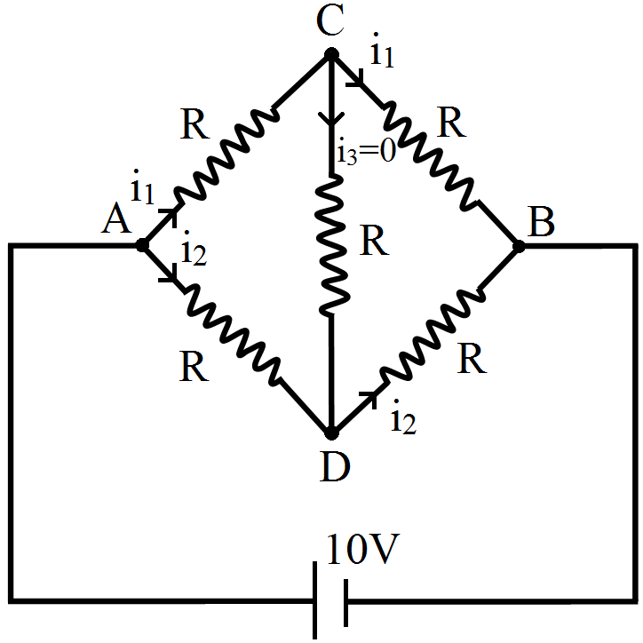
- The equivalent circuit is shown in fig. It is a balanced Wheatstone bridge.
So, the resistance connected between C and D is ineffective.
Resistance of arm ACB, $R_1 = R + R = 2R$
Resistance of arm ADB, $R_2 = R + R = 2R$
Equivalent resistance between A and B, RAB is given by
$\frac{1}{\text{R}_\text{AB}}=\frac{1}{2\text{R}}+\frac{1}{2\text{R}}=\frac{2}{2\text{R}}$
$\Rightarrow\text{R}_\text{AB}=\text{R}=2\Omega$
- In arm CD, there is no current, ICD = 0,
Current through arm ACB
$\text{i}_1=\frac{\text{V}}{\text{R}_1}$
$=\frac{10}{2\text{R}}=\frac{10}{2\times2}=\frac{10}{4}=2.5\text{A}$ View full question & answer→Question 605 Marks
A copper wire of radius 0.1mm and resistance $1\text{k}\Omega$ is connected across a power supply of 20V.
(a) How many electrons are transferred per second between the supply and the wire at one end? (b) Write down the current density in the wire.
Answer$\text{r}=0.1\text{mm}=10^{-4}\text{m}$
$\text{R}=1\text{K}\Omega=10^3\Omega,\text{V}=20\text{V}$
- No.of electrons transferred
$\text{i}=\frac{\text{V}}{\text{R}}=\frac{20}{10^3}=20\times10^{-3}=2\times10^{-2}\text{A}$
$\text{q}=\text{it}=2\times10^{-2}\times1=2\times10^{-2}\text{C}$
No. of electrons transferred $=\frac{2\times10^{-2}}{1.6\times10^{-19}}=\frac{2\times10^{-17}}{1.6}=1.25\times10^{17}.$
- Current density of wire
$=\frac{\text{i}}{\text{A}}=\frac{2\times10^{-2}}{\pi\times10^{-8}}=\frac{2}{3.14}\times10^6$
$=0.6369\times10^6=6.37\times10^5\text{A}/\text{m}^2.$ View full question & answer→Question 615 Marks
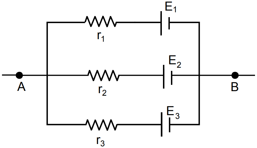
Two cells of same emf E but internal resistance $r_1$ and $r_2$ are connected in series to an external resistor R (Fig). What should be the value of R so that the potential difference across the terminals of the first cell becomes zero.
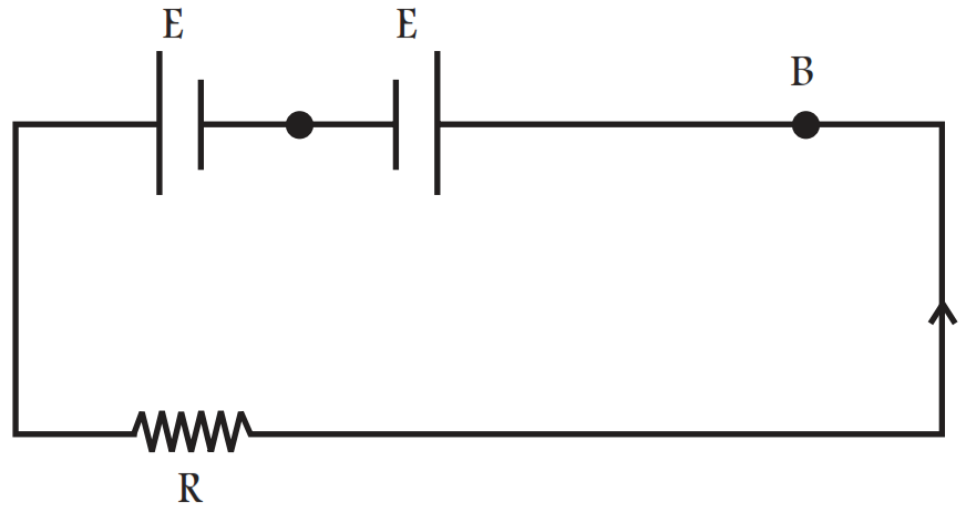
AnswerIn this problem first we apply Ohm's law to find
current in the circuit.
Effective emf of two cells $= E + E = 2E$
Effective Resistance $= R + r_1 + r_2$
So the electric current is given by
$\text{I}=\frac{\text{E}+\text{E}}{\text{R}+\text{r}_1+\text{r}_2}$
The potential difference across the termibals of the first cell and putting it equal to zero.
$\text{V}_1=\text{E}-\text{Ir}_1=\text{E}-\frac{2\text{E}}{\text{r}_1+\text{r}_2+\text{R}}\text{r}_1=0$
$\text{E}=\frac{2\text{E}\text{r}_1}{\text{r}_1+\text{r}_2\text{R}}\Rightarrow1=\frac{2\text{r}_1}{\text{r}_1+\text{r}_2+\text{R}}$
or $\text{r}_1+\text{r}_2+\text{R}=2\text{r}_1\Rightarrow\ \text{R}=\text{r}_1-\text{r}_2.$
View full question & answer→Question 625 Marks
The emf $\in$ and the internal resistance r of the battery, shown in the figure. are 4.3V and $1.0\Omega$ respectively. The external resistance R is $50\Omega.$ The resistances of the ammeter and voltmeter are $2.0\Omega$ and $200\Omega$ respectively. (a) Find the readings of the two $200\Omega$ respectively. (a) Find the readings of the two meters. (b) The switch is thrown to the other side. What will be the readings of the two meters now?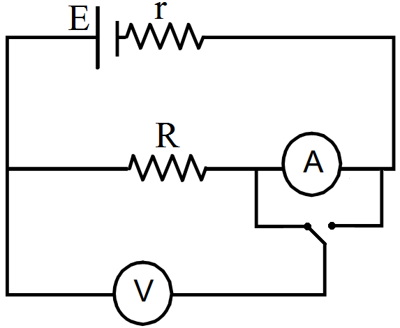
Answer
- In circuit ABFGA,
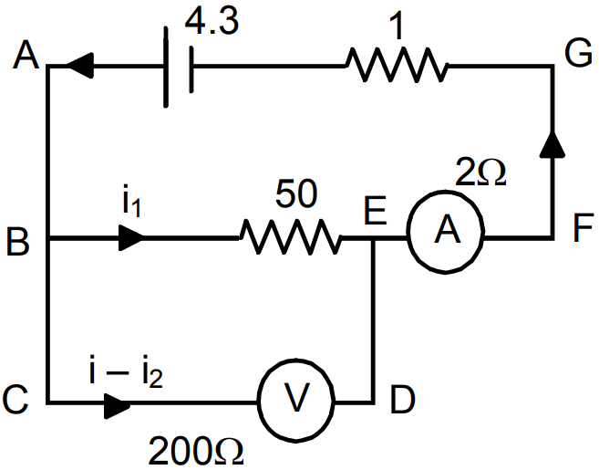
$\text{i}_150+2\text{i}+\text{i}-4.3=0$
$\Rightarrow50\text{i}_1+3\text{i}=4.3\ ...(1)$
In circuit BEDCB,
$50\text{i}-200\text{i}+200\text{i}_1=0$
$\Rightarrow250\text{i}_1-200\text{i}=0$
$\Rightarrow50\text{i}_1-40\text{i}=0\ ...(2)$
From (1) and (2)
$43\text{i}=4.3\Rightarrow\text{i}=0.1$
$5\text{i}_1=4\times\text{i}=4\times0.1$
$\Rightarrow\text{i}_1=\frac{4\times0.1}{5}=0.08\text{A}$
Ammeter reads a current $=\text{i}=0.1\text{A}$
Voltmeter reads a potential difference equal to $\text{i}_1\times50=0.08\times50=4\text{V}.$
- In circuit ABEFA,
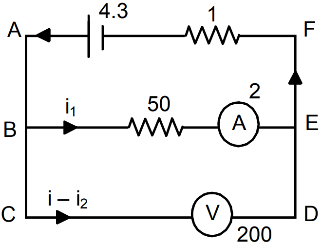
$50\text{i}_1+2\text{i}_1+1\text{i}-4.3=0$
$\Rightarrow52\text{i}_1+\text{i}=4.3$
$\Rightarrow200\times52\text{i}_1+200\text{i}=4.3\times200\ ...(1)$
In circuit BCDEB,
$(\text{i}-\text{i}_1)200-\text{i}_12-\text{i}_150=0$
$\Rightarrow200\text{i}-200\text{i}_1-2\text{i}_1-50\text{i}_1=0$
$\Rightarrow200\text{i}-252\text{i}_1=0\ ...(2)$
From (1) and (2)
$\text{i}_1(10652)=4.3\times2\times100$
$\Rightarrow\text{i}_1=\frac{4.3\times2\times100}{10652}=0.08$
$\text{i}=4.3-52\times0.08=0.14$
Reading of the ammeter = 0.08a
Reading of the voltmeter $=(\text{i}-\text{i}_1)200=(0.14-0.08)\times200=12\text{V}.$ View full question & answer→Question 635 Marks
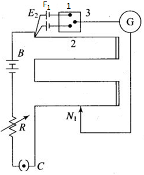
Figure shows a potentiometer circuit for comparison of two resistances. The balance point with a standard resistance $\text{R}=10.0\Omega$ is found to be 58.3cm, while that with the unknown resistance X is 68.5cm. Determine the value of X. What might you do if you failed to find a balance point with the given cell $\varepsilon.$
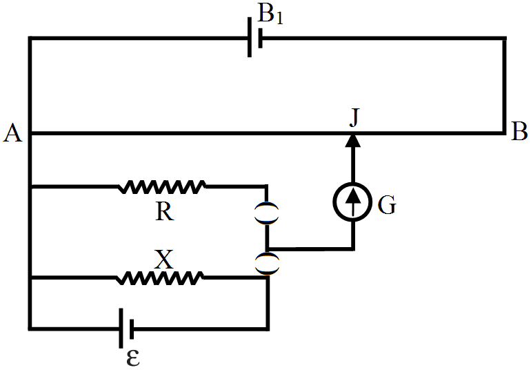
AnswerIn first case, resistance R is in parallel with cell $\varepsilon,$ so p.d. across $\text{R}=\varepsilon$
i.e., $\varepsilon$ = RI ...(i)
In second case, X is in parallel with cell so p.d. across $\text{X}=\varepsilon$
i.e., $\varepsilon$ = XI ...(ii)
Let k be the potential gradient of potentiometer wire. If $l_1$ and $l_2$ are the balancing length
corresponding to resistance respectively, then
$\varepsilon = kl_1 ...(iii)$
$\varepsilon = kl_2 ...(iv)$
From $(i)$ and $(iii) RI = kl_1 ...(v)$
From $(ii)$ and $(iv) XI = kl_2 ...(vi)$
Dividing (vi) by (v), we get
$\frac{\text{X}}{\text{R}}=\frac{\text{l}_2}{\text{l}_1}\Rightarrow\text{X}=\frac{\text{l}_2}{\text{l}_2}\text{R}$
Here, $\text{R} = 10.0 \Omega, \text{l}_1 = 58.3\text{cm}, \text{l}2 = 68.5 \text{cm}$
$\therefore\text{X}=\frac{68.5}{58.3}\times10.0=11.75\Omega$
If we fail to find the balance point with the given cell ε, then we shall take the driver battery $(B_1)$ of higher emf than given emf $(\varepsilon).$
View full question & answer→Question 645 Marks
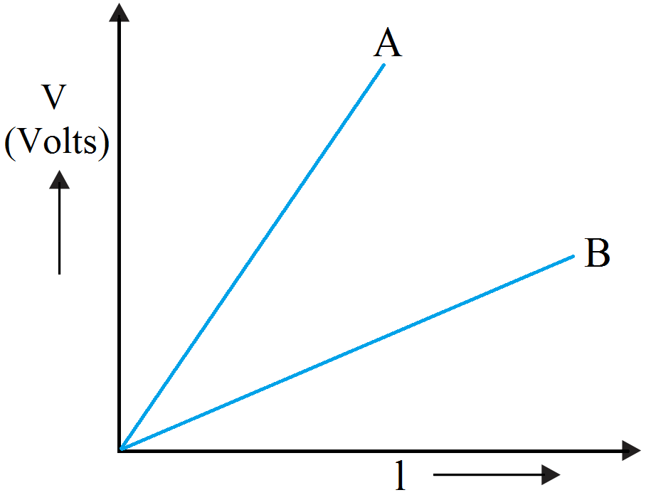
Define resistivity of a conductor. Plot a graph showing the variation of resistivity with temperature for a metallic conductor. How does one explain such a behaviour, using the mathematical expression of the resistivity of a material?
AnswerWe know that, $\text{R}=\rho\frac{\text{l}}{\text{A}}$ If $\text{l}=\text{1},\text{A}=1\Rightarrow\rho=\text{R}$ Thus, resistivity of a material is numerically equal to the resistance of the conductor having unit length and unit cross-sectional area. The resistivity of a material is found to be dependent on the temperature. Different materials do not exhibit the same dependence on temperature. Over a limited range of temperatures, that is not too large, the resistivity of a metallic conductor is approximately given by, $\rho_\text{T}={\rho_0}[{1}+\alpha(\text{T}-\text{T}_0)]\dots\text{(i)}$ Where $\rho_\text{T}$ is the resistivity at a temperature T and $\rho_0$ is the same at a reference temperature $\text{T}_0,\alpha$ is called the temperature co-efficient of resistivity. Relation (i) implies that a graph of $\rho_\text{T}$ plotted against T would be a straight line. At temperatures much lower than 0°C, the graph, however, deviates considerably from a straight line (Fig.).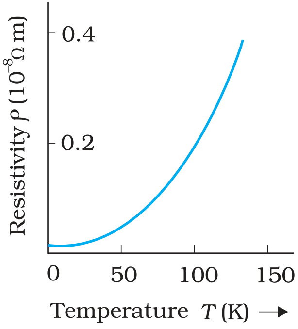
Resistivity $\rho_\text{T}$ of metallic conductor as a function of temperature T. View full question & answer→Question 655 Marks
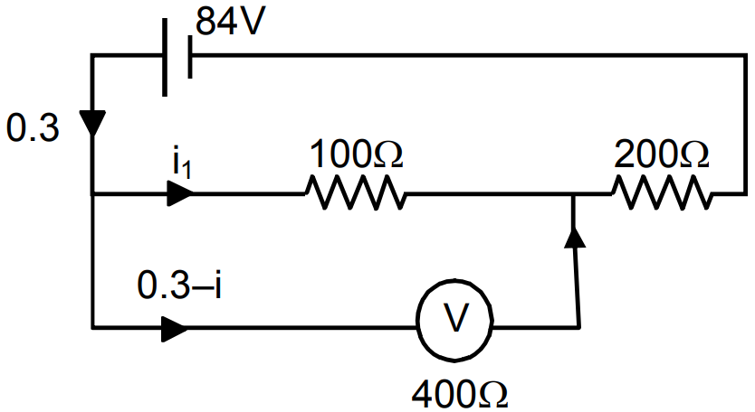
A voltmeter of resistance $400\Omega$ is used to measure the potential difference across the $100\Omega$ resistor in the circuit shown in the figure. (a) What will be the reading of the voltmeter? (b) What was the potential difference across $100\Omega$ before the voltmeter was connected?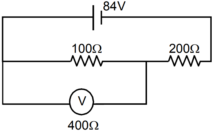
Answer
- $\text{R}_\text{eff}=\frac{100\times400}{500}+200=280$
$\text{i}=\frac{84}{280}=0.3$
$100\text{i}=(0.3-\text{i})400$
$\Rightarrow\text{i}=1.2-4\text{i}$
$\Rightarrow5\text{i}=1.2\Rightarrow\text{i}=0.24$
Voltage measured by the voltmeter $=\frac{0.24\times100}{24\text{V}}$
- If voltmeter is not connected
$\text{R}_\text{eff}=(200+100)=300\Omega$
$\text{i}=\frac{84}{300}=0.28\text{A}$
Voltage across $100\Omega=(0.28\times100)=28\text{V}.$ View full question & answer→Question 665 Marks
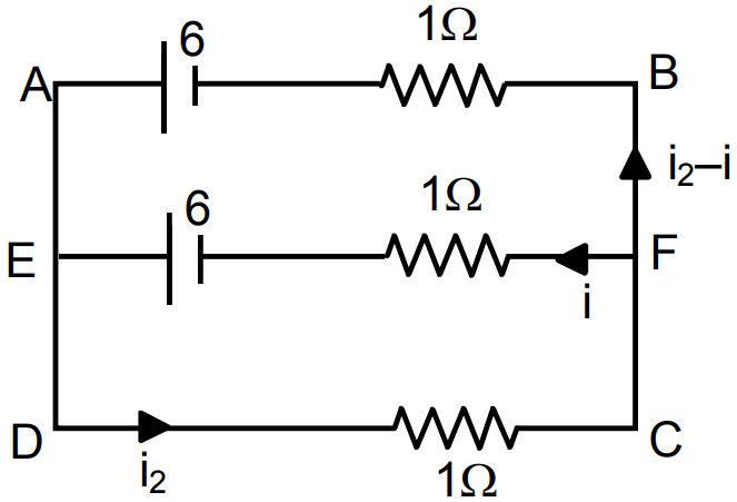
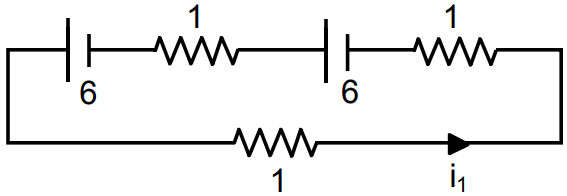
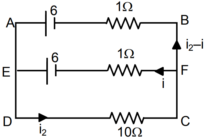
Find the value of $\frac{\text{i}_1}{\text{i}_2}$ in the figure. if (a) $\text{R}=0.1\Omega$ (b) $\text{R}=1\Omega$ and (c) $\text{R}=10\Omega.$ Note from your answers that in order to get more current from a combination of two batteries, they should be joined in parallel if the external resistance is small and in series if the external resistance is large, compared to the internal resistance.
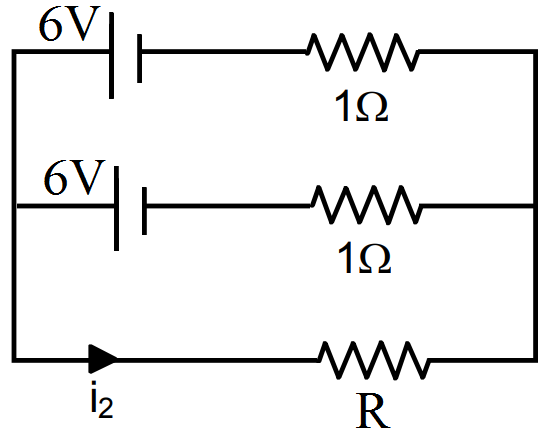
Answer
- $0.1\text{i}_1+1\text{i}_1-6+1\text{i}_1-6=0$
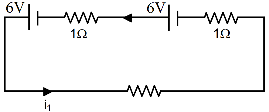
$\Rightarrow0.1\text{i}_1+1\text{i}_1+1\text{i}_1=12$
$\Rightarrow\text{i}_1=\frac{12}{2.1}$
$\text{ABCDA}$
$\Rightarrow0.1\text{i}_2+1\text{i}-6=0$
$\Rightarrow0.1\text{i}_2+1\text{i}$
$\text{ADEFA}$
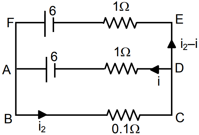
$\Rightarrow\text{i}-6+6-(\text{i}_2-\text{i})1=0$
$\Rightarrow\text{i}-\text{i}_2+\text{i}=0$
$\Rightarrow2\text{i}-\text{i}_2=0\Rightarrow-2\text{i}\pm0.2\text{i}=0$
$\Rightarrow\text{i}_2=0.$
- $1\text{i}_1+1\text{i}_1-6+1\text{i}_1=0$
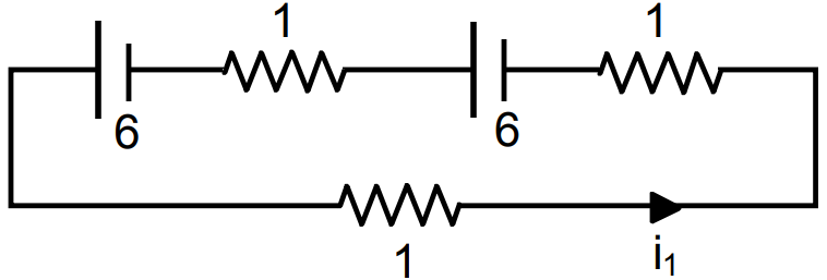
$\Rightarrow3\text{i}_1=12\Rightarrow\text{i}_1=4$
$\text{DCFED}$
$\Rightarrow\text{i}_2+\text{i}-6=0\Rightarrow\text{i}_2+\text{i}=6$
$\text{ABCDA}$
$\text{i}_2+(\text{i}_2-\text{i})-6=0$
$\Rightarrow\text{i}_2+\text{i}_2-\text{i}=6\Rightarrow2\text{i}_2-\text{i}=6$
$\Rightarrow-2\text{i}_2\pm2\text{i}=6\Rightarrow\text{i}=-2\text{i}_2+\text{i}=6$
$\Rightarrow\text{i}_2-2=6\Rightarrow\text{i}_2=8$
$\frac{\text{i}_1}{\text{i}_2}=\frac{4}{8}=\frac{1}{2}.$
- $10\text{i}_1+1\text{i}_1-6+1\text{i}_1-6=0$
$\Rightarrow12\text{i}_1=12\Rightarrow\text{i}_1=1$
$10\text{i}_2-\text{i}_1-6=0$
$\Rightarrow10\text{i}_2-\text{i}_1=6$
$\Rightarrow10\text{i}_2+(\text{i}_2-\text{i})1-6=0$
$\Rightarrow11\text{i}_2=6$
$\Rightarrow-\text{i}_2=0.$
View full question & answer→Question 675 Marks
A $100\mu\text{F}$ capacitor is joined to a 24V battery through a $1.0\text{M}\Omega$ resistor. Plot qualitative graphs (a) between current and time for the first 10 minutes and (b) between charge and time for the same period.
AnswerTime constant $\text{RC} = 1 \times 10^6 \times 100 \times 10^6 = 100 \text{sec}$
- $\text{q}=\text{VC}\Big(1-\text{e}^{\frac{-\text{t}}{\text{CR}}}\Big)$
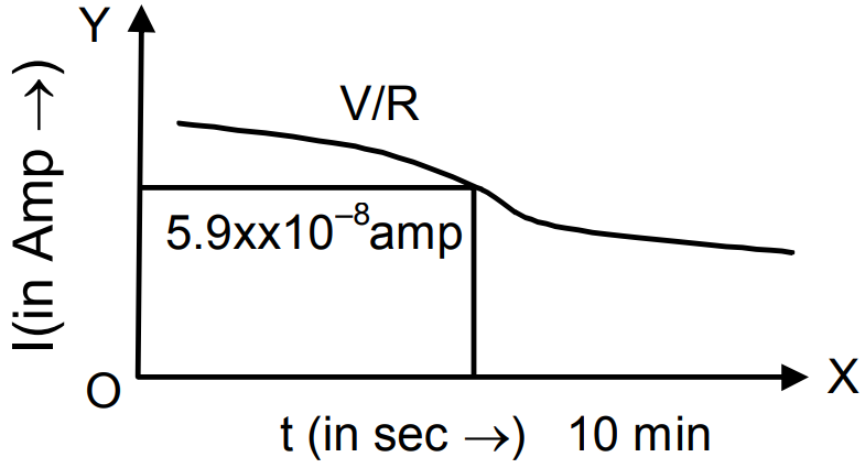
I = Current $=\frac{\text{dq}}{\text{dt}}=\text{VC}.(-)\text{e}^{\frac{-\text{t}}{\text{RC}}},\frac{-1}{\text{RC}}$
$=\frac{\text{V}}{\text{R}}\text{e}^{\frac{-\text{t}}{\text{RC}}}=\frac{\text{V}}{\text{R}\cdot\text{e}^{\frac{\text{t}}{\text{RC}}}}=\frac{24}{10^6}\times\frac{1}{\text{e}^{\frac{\text{t}}{100}}}$
$=24\times10^{-6}\frac{1}{\text{e}^{\frac{\text{t}}{100}}}$
$\text{t}=10\text{min},600\text{sec}.$
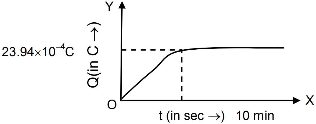
$\text{Q}=24\times10+-4\times\big(1-\text{e}^{-6}\big)=23.99\times10^{-4}$
$\text{I}=\frac{24}{10^6}\times\frac{1}{\text{e}^6}=5.9\times10^{-8}\text{Amp}.$
- $\text{q}=\text{VC}\Big(1-\text{e}^\frac{-\text{t}}{\text{CR}}\Big)$
View full question & answer→Question 685 Marks
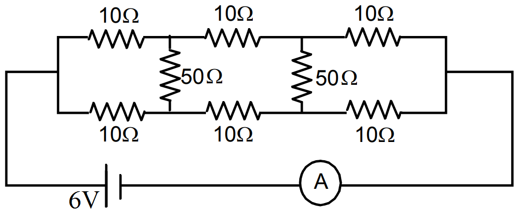
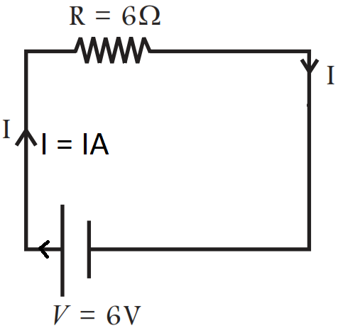
Find the current measured by the ammeter in the circuit shown in the figure.
Answer
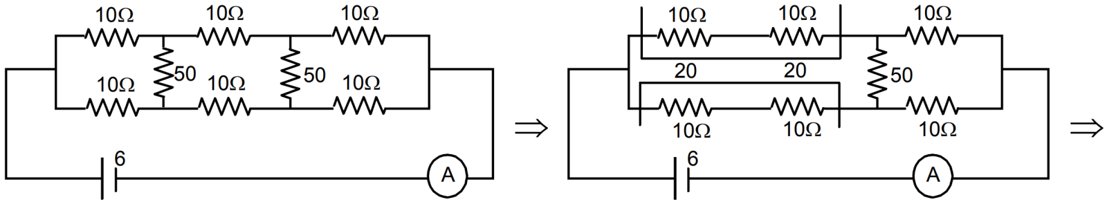
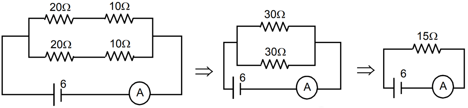 $\text{I}=\frac{6}{15}=\frac{2}{5}=0.4\text{A}.$
 View full question & answer→Question 695 Marks
Twelve wires, each of equal resistance r, are joined to form a cube, as shown in the figure. Find the equivalent resistance between the diagonally opposite points a and f.
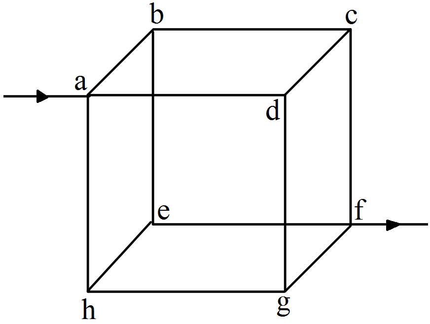
AnswerTaking circuit ABHGA,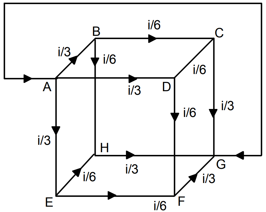
$\frac{\text{i}}{3\text{r}}+\frac{\text{i}}{6\text{r}}+\frac{\text{i}}{3\text{r}}=\text{V}$ $\Rightarrow\Big(\frac{2\text{i}}{3}+\frac{\text{i}}{6}\Big)\text{r}=\text{V}$ $\Rightarrow\text{V}=\frac{5\text{i}}{6}\text{r}$ $\Rightarrow\text{R}_\text{eff}=\frac{\text{V}}{\text{i}}=\frac{5}{6\text{r}}$ View full question & answer→Question 705 Marks
The voltmeter shown in the figure. reads 18V across the $50\Omega$ resistor. Find the resistance of the voltmeter.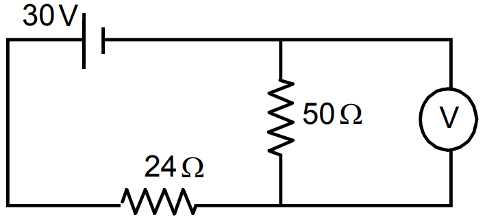
AnswerLet resistance of the voltmeter be $\text{R}\Omega$
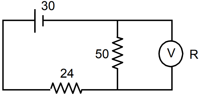
$\text{R}_1=\frac{50\text{R}}{50+\text{R}},\text{R}_2=24$
Both are in series.
$30=\text{V}_1+\text{V}_2$
$\Rightarrow30=\text{iR}_1+\text{iR}_2$
$\Rightarrow30-\text{iR}_2=\text{iR}_1$
$\Rightarrow\text{iR}_1=30-\frac{30}{\text{R}_1+\text{R}_2}\text{R}_2$
$\Rightarrow\text{V}_1=30\Big(1-\frac{\text{R}_2}{\text{R}_1+\text{R}_2}\Big)$
$\Rightarrow\text{V}_1=30\Big(\frac{\text{R}_1}{\text{R}_1+\text{R}_2}\Big)$
$\Rightarrow18=30\Bigg(\frac{50\text{R}}{50+\text{R}\Big(\frac{50\text{R}}{50+\text{R}}+24\Big)}\Bigg)$
$\Rightarrow18=30\bigg(\frac{50\text{R}\times(50+\text{R})}{(50+\text{R})+(50\text{R}+24)(50+\text{R})}\bigg)$ $=\frac{30(50\text{R})}{50\text{R}+1200+24\text{R}}$
$\Rightarrow18=\frac{30\times50\times\text{R}}{74\text{R}+1200}=18(74\text{R}+1200)=1500\text{R}$
$\Rightarrow1332\text{R}+21600=1500\text{R}$
$\Rightarrow21600=1.68\text{R}$
$\Rightarrow\text{R}=\frac{21600}{168}=128.57.$ View full question & answer→Question 715 Marks
Consider the potentiometer circuit as arranged in the figure. The potentiometer wire is 600cm long. (a) At what distance from the point A should the jockey touch the wire to get zero deflection in the galvanometer? (b) If the jockey touches the wire at a distance of 560cm from A, what will be the current in the galvanometer?
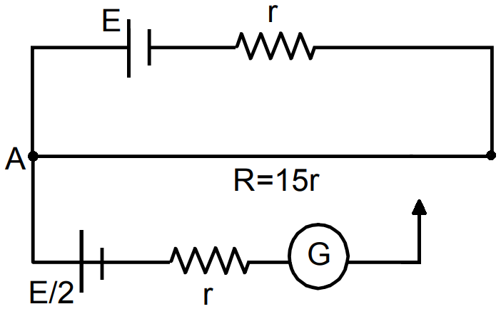
AnswerResistance per unit length $=\frac{14\text{r}}{6}$
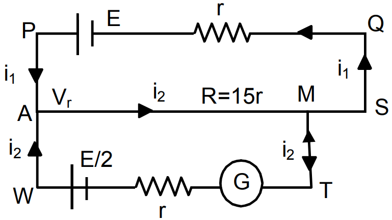
For length x, $\text{Rx}=\frac{15\text{r}}{6}\times\text{x}$
- For the loop PASQ $(\text{i}_1+\text{i}_2)\frac{15}{6}\text{rx}+\frac{15}{6}(6-\text{x})\text{i}_1+\text{i}_1\text{R}=\text{E}\ ...(1)$
For the loop AWTM, $-\text{i}_2.\text{R}-\frac{15}{6}\text{rx}(\text{i}_1+\text{i}_2)=\frac{\text{E}}{2}$
$\Rightarrow\text{i}_2\text{R}+\frac{15}{6}\text{r}\times(\text{i}_1+\text{i}_2)=\frac{\text{E}}{2}\ ...(2)$
For zero deflection galvanometer $\text{i}_2=0\Rightarrow\frac{15}{6}\text{rx}.\text{i}_1=\frac{\text{E}}{2}=\text{i}_1=\frac{\text{E}}{5\text{x}.\text{r}}$
Putting $\text{i}_1=\frac{\text{E}}{5\text{x . r}}$ and $i_2 = 0$ in equation (1), we get x = 320cm.
- Putting x = 5.6 and solving equation (1) and (2) we get $\text{i}_2=\frac{3\text{E}}{22\text{r}}.$
View full question & answer→Question 725 Marks
Determine the current in each branch of the network shown in Fig.:
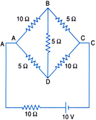
AnswerConsider the mesh ABDA, Now, Applying Kirchhoff's loop rule we get, $-10\text{I}_1-5\text{I}_\text{g}+(\text{I}-\text{I}_1)5=0$ $\Rightarrow\ \ 3\text{I}_1-\text{I}+\text{I}_\text{g}=0\ \ ...\text{(i)}$
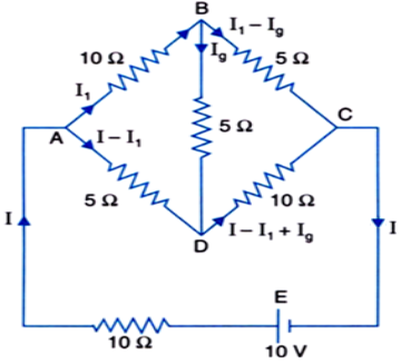
Consider the mesh BDCB, Again, applying Kirchhoff's loop rule we get,
$-5\text{I}_\text{g}-10(1-\text{I}_\text{l}+\text{I}_\text{g})+5(\text{I}_\text{I}-\text{I}_\text{g})=0$
$\Rightarrow\ \ 3\text{I}_1-2\text{I}-4\text{I}_\text{g}=0\ \ ...\text{(ii)}$
Applying Kirchhoff's loop rule to the mesh ABCEA, $-10\text{I}_1-5(\text{I}_1-\text{I}_\text{g})-10\text{I}+10=0$ $\text{or}\ \ 3\text{I}_1+2\text{I}-\text{I}_\text{g}=2\ \ ...{(\text{iii})}$ Equations (i), (ii) and (iii) are simultaneous equations.
On solving these equations, we will find the unknown values of current.
Adding (i) and (iii), we get $6\text{I}_\text{1}+\text{I}=2\ \ ...(\text{iv})$
Multiplying (i) by 4 and adding in (ii),
we get $15\text{I}_\text{1}-6\text{I}0=0\ \ ...\text{(v)}$
Solving equations (iv) and (v), we get $\text{I}_1=\frac{4}{17}\text{A}=0.235\ \text{A}$
So, current in branch AB is 0.235 A. Putting the value of $I_1$ in equation (v) and simplifying,
we get Total current, $\text{I}=\frac{10}{17}=0.588\ \text{A}$
Putting the values of I and $I_1$ in equation (iii) and simplifying,
we get $\text{I}_\text{g}=\frac{2}{17}\text{A}=-0.118\ \text{A}$
The negative sign indicates that the direction of current is opposite to that shown in Fig.
above. So, current in branch BD is -0.118 A.
Current in branch BC is $(\text{I}_1-\text{I}_\text{g})\text{i.e}.,\frac{4}{17}-\Big(-\frac{2}{17}\Big)$
$\text{i.e.,}\frac{6}{17}\ \text{or}\ 0.353\ \text{A}.$ Current in branch AD is $(I - I_1)$
$\text{i.e.,}\Big(\frac{10}{17}-\frac{4}{17}\Big)\text{A i.e.,}\ \frac{6}{17}\text{A or}\ 0.353\ \text{A}$
Current in branch DC is $ (I_1 - I_1 + I_g)$
$\text{i.e.,}\frac{6}{17}+\Big(-\frac{2}{17}\Big)\text{A or}\ \frac{4}{17}\text{A or}\ 0.235\ \text{A}.$ View full question & answer→Question 735 Marks
In a practical Wheatstone bridge circuit, wire AB is 2m long. When resistance Y = 2.0W and jockey is in position J such that AJ = 1.20m, there is no current in galvanometer, find the value of unknown resistance X. The resistance per unit length of wire AB = 0.01W/cm. Also calculate the current drawn by the cell of emf 4.0V and negligible internal resistance.
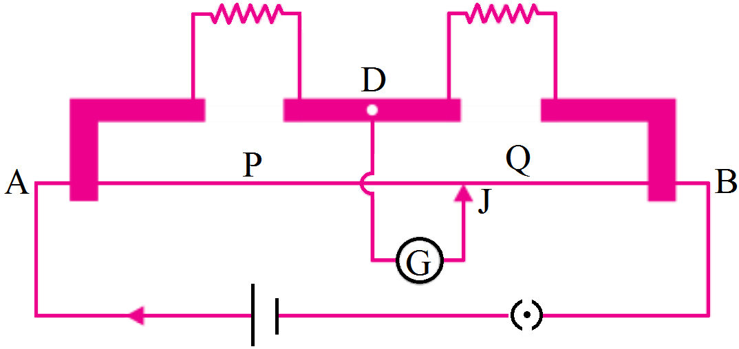
AnswerP = Resistance of wire AJ
$=(1.20\times100\text{cm})\times(0.01\Omega/\text{cm})=1.20\Omega$
Q = Resistance of wire BJ
$= [(2-1.20)m × 100] × $resistance per cm
$=0.80\times100\text{cm}\times0.1\Omega=0.80\Omega$
$\text{Y}=2.0\Omega,\text{X}=?$
When no current flows through the galvanometer, the bridge is balanced so
$\frac{\text{P}}{\text{Q}}=\frac{\text{X}}{\text{Y}}\Rightarrow\text{X}=\frac{\text{P}}{\text{Q}}\text{Y}\text{ or X}=\frac{1.20}{0.80}\times2.0=3.0\Omega $
Total resistance of X and Y connected in series,
$\text{R}_1=\text{X}+\text{Y}=3.0+2.0=5.0\Omega$
Total resistance of P and Q connected in series (or wire AB)
$\text{R}_2=2\times100\times0.1=2.0\Omega$
The resistance $R_1$ and $R_2$ are in parallel, so effective resistance between terminals A and B of bridge is
$\text{R}_\text{AB}=\frac{\text{R}_1\text{R}_2}{\text{R}_1+\text{R}_2}=\frac{5.0\times2.0}{5.0+2.0}=\frac{10}{7}\Omega$
Current drawn from battery $\text{I}=\frac{\varepsilon}{\text{R}_\text{AB}}=\frac{4.0}{\frac{10}{7}}=2.8\text{A}$
View full question & answer→Question 745 Marks
Two heaters are marked 200V, 300W and 200V, 600W. If the heaters are connected in series and the combination connected to a 200V dc supply, which heater will produce more heat?
AnswerResitance of heaters $\text{R}_1=\frac{\text{V}^2}{\text{P}_1}=\frac{(200)^2}{300}=\frac{400}{3}\Omega$
$\text{R}_2=\frac{\text{V}^2}{\text{P}_2}=\frac{(200)^2}{600}=\frac{400}{6}\Omega$
When heaters are connected in series, current in circuit,
$\text{I}=\frac{\text{V}}{\text{R}_1+\text{R}_2}=\frac{200}{\frac{400}{3}+\frac{400}{6}}=1\text{A}$
Heat product in 200V, 300W heater per second,
$\text{Q}_1=\text{I}^2\text{R}_1=(1)^2\times\frac{400}{3}=133.33\text{Js}^{-1}$
Heat produced in 200V, 600W heater per second,
$\text{Q}_2=\text{I}^2\text{R}_2=(1)^2\times\frac{400}{6}=66.66\text{Js}^{-1}$
Clearly heat produced in 300W heater is more that produced in 600W heater.
View full question & answer→Question 755 Marks
The switch S shown in figure. is kept closed for a long time and is then opened at t = 0. Find the current in the middle $1.0\Omega$ resistor at t = 1ms.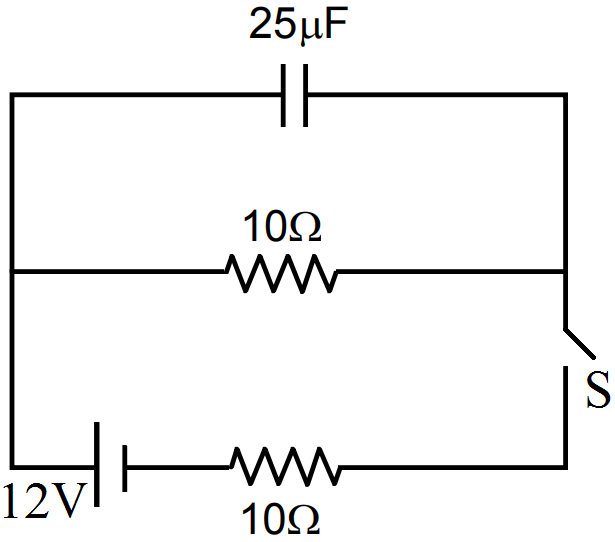
AnswerIn steady state condition, no current passes through the $25\mu\text{F}$ capacitor,
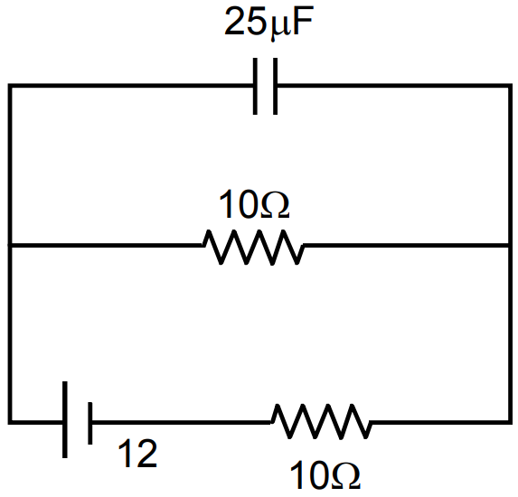
$\therefore$ Net resistance $=\frac{10\Omega}{2}=5\Omega$
Potential difference across the capacitor = 5
Potential difference across the $10\Omega$ resistor
$=\frac{12}{5}\times10=24\text{V}$
$\text{q}=\text{Q}\Big(\text{e}^{\frac{-\text{t}}{\text{RC}}}\Big)=\text{V}\times\text{C}\Big(\text{e}^{\frac{-\text{t}}{\text{RC}}}\Big)$ $=24\times25\times10^{-6}\bigg[\text{e}^{\frac{-1\times10^{-3}}{10\times25\times10^{-4}}}\bigg]$
$=24\times25\times10^{-6}\text{e}^{-4}$
$=24\times25\times10^{-6}\times0.0183=10.9\times10^{-6}\text{C}$
Charge given by the capacitor after time t.
Current in the $10\Omega$ resistor $=\frac{10.9\times10^{-6}\text{C}}{1\times10^{-3}\text{sec}}=11\text{mA}.$ View full question & answer→Question 765 Marks
Two cells of emf 1V, 2V and internal resistances $2\Omega$ and $1\Omega$ respectively are connected in (i) series. (ii) Parallel. What should be the external resistance in the circuit so that the current through the resistance be the same in the two cases? In which case is more heat generated in the cells?
AnswerFor parallel combination,
Net emf, $\varepsilon=\frac{\varepsilon_1\text{r}_1+\varepsilon_2\text{r}_2}{\text{r}_1+\text{r}_2}$
Net internal resistance, $\text{r}_\text{int}=\frac{\text{r}_1\text{r}_2}{\text{r}_1+\text{r}_2}$
For series combination,
Net emf, $\varepsilon=\varepsilon_1+\varepsilon_2$
Net internal resistance rint $=\text{r}_1+\text{r}_2$
Given, $\varepsilon_1=1\text{V},\varepsilon_2=2\text{V}$ and $\text{r}_1=2\Omega,\text{r}_2=1\text{}\Omega,\text{Rext}=\text{R}$
$\therefore$ Current, $\text{I}_1=\frac{\varepsilon_1+\varepsilon_2}{\text{r}_1+\text{r}_2+\text{R}}=\frac{1+2}{2+1+\text{R}}=\frac{3}{3+\text{R}}\text{A}\dots\text{(i)}$
Current, $\text{I}_2=\frac{\frac{(\varepsilon_1\text{r}_2+\varepsilon_2\text{r}_1)}{(\text{r}_1+\text{r}_2}}{\text{R}\Big\{\frac{(\text{r}_1\text{r}_2)} {(\text{r}_1+\text{r}_2}\Big\}}\dots\text{(ii)}$
$=\frac{\frac{(1\times1+2\times2)}{(2+1)}}{\text{R}+\frac{2\times1}{2+1}}=\frac{\frac53}{\text{R}+\frac23}=\frac{5}{3\text{R}+2}$
Given, $I_1 = I_2$
$\therefore\frac{3}{3+\text{R}}=\frac{5}{3\text{R}+2}\text{ or }9\text{R}+6=15+5\text{R}$
$\text{4R}=9\Rightarrow\text{R}=\frac{9}{4}=2.25\Omega$
Heat generated in external resistance $(I^2R)$ is same in both cases but heat generated in cells $(I^2$ rint$)$ is more in series than that in parallel combination of cells.
View full question & answer→Question 775 Marks
In the circuit shown in the figure. $\in_1=3\text{V},\in_2=2\text{V},\in_3=1\text{V}$ and $\text{r}_1=\text{r}_2=\text{r}_3=1\Omega.$ Find the potential difference between the points A and B and the current through each branch.
AnswerIn circuit ABDCA,
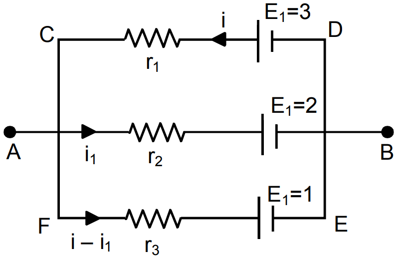
$\text{i}_1+2-3+\text{i}=0$
$\Rightarrow\text{i}+\text{i}_1-1=0\ ...(1)$
In circuit CFEDC,
$(\text{i}-\text{i}_1)+1-3+\text{i}=0$
$\Rightarrow2\text{i}-\text{i}_1-2=0\ ...(2)$
From (1) and (2)
$3\text{i}=3\Rightarrow\text{i}=1\text{A}$
$\text{i}_1=1-\text{i}=0\text{A}$
$\text{i}-\text{i}_1=1-0=1\text{A}$
Potential difference between A and B
$=\text{E}-\text{ir}=3-1.1=2\text{V}.$ View full question & answer→Question 785 Marks
Explain the variation of conductivity with temperature for:
- A metallic conductor.
- Ionic conductors.
- Semiconductors.
AnswerConductivity of a metallic conductor $\sigma=\frac{1}{\rho}=\frac{\text{ne}^2\tau}{\text{m}}.$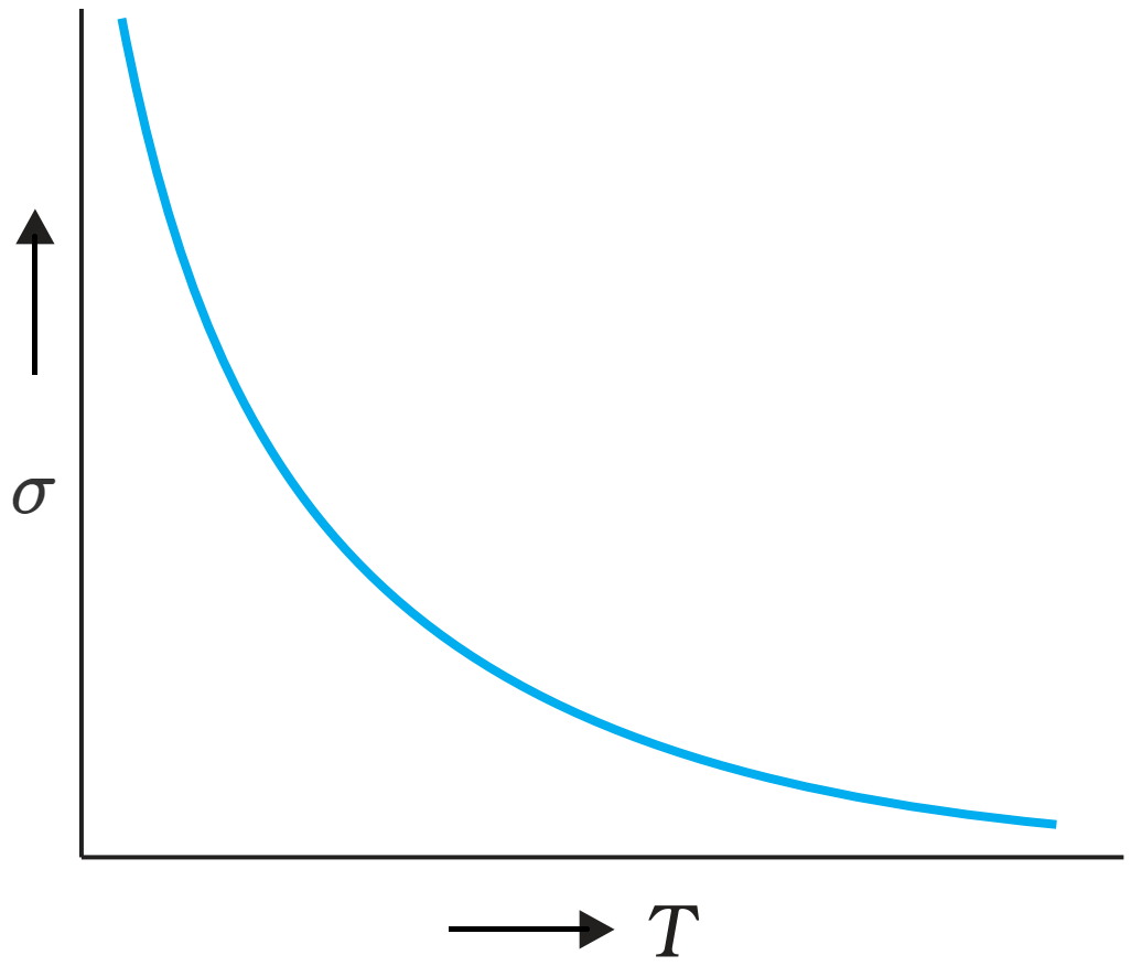
Where m = mass of charge carrier, e = charge on each carrier $\tau$ = relaxation time, n = number density of charge carriers
- With rise of temperature, the collision of electrons with fixed lattice ions/ atoms increases so that relaxation time $(\tau)$ decreases. Consequently, the conductivity of metals decreases with rise of temperature.
- Conductivity of ionic conductor increases with increase of temperature because with increase of temperature, the ionic bonds break releasing positive and negative ions which are charge carriers in ionic conductors.
- In the case of a semiconductors, when temperature increases, covalent bonds break and charge carriers (electrons and holes) become free i.e., n increases, so conductivity increases with rise of temperature.
View full question & answer→Question 795 Marks
For the circuit shown here, calculate the potential difference between points B and D.
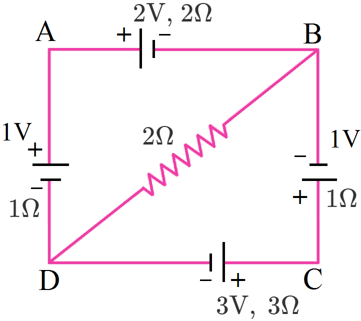
AnswerAccording to Kirchhoff’s first law the distribution of currents is shown in fig.
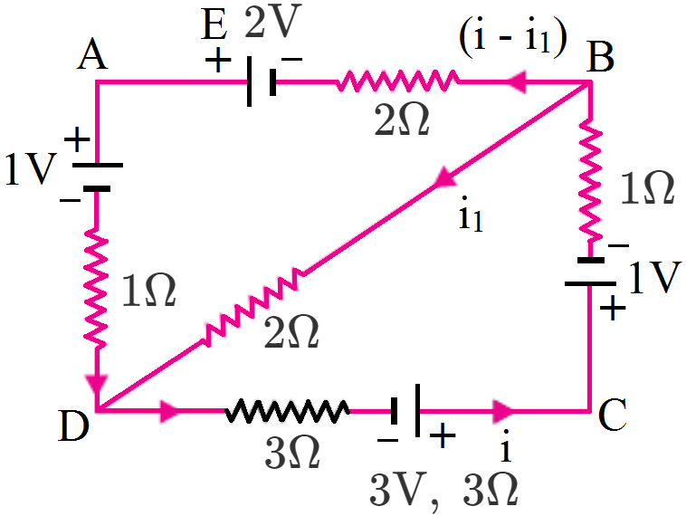
Applying Kirchhoff’s second law to mesh BADB, $–2(i – i_1) +2 – 1 – 1. (i – i_1) + 2i_1 = 0$
$\Rightarrow 3i – 5i_1 = 1 …(i)$
Applying Kirchhoff’s law to mesh DCBD, $-3i + 3 - 1 - 1\times i - 2i_1 = 0$
$\Rightarrow 4i + 2i_1 = 2$ Or $2i + i_1 = 1 …(ii)$
Multiplying equation (ii) with 5, we get
$10i + 5i_1 = 5 …(iii)$
Adding (i) and (iii), we get $13\text{i}=6\Rightarrow\text{i}=\frac{6}{13}\text{A}$
From (ii), $\text{i}_1=1-2\text{i}=1-\frac{12}{13}=\frac{1}{13}\text{A}$
Potential difference between B and D is,
$\text{V}_\text{n}-\text{v}_\text{n}=\text{i}-1\times2=\frac{2}{13}\text{V}$ View full question & answer→Question 805 Marks
The relaxation time τ is nearly independent of applied E field whereas it changes significantly with temperature T. First fact is (in part) responsible for Ohm’s law whereas the second fact leads to variation of ρ with temperature. Elaborate why?
AnswerKey concept: Time interval between two successive collisions of electron with positive ions in the metallic lattice is defined as relaxation time $\tau=\frac{\text{mean free path}}{\text{r. m. s. velocity of electrons}}=\frac{\lambda}{\text{v}_\text{rms}}$ with rise in tempereture $v_{rms} $ increase consequently as $\tau$ decreases.
The drift velocity of the elecrons is small because of the frequent collisions suffered by electrons.
Relaxation time is inversely proportional to the velocities of electorns ans ions. The applied electric field produces the insignificant change in velocities of electrons at the order of 1 mm/s, whereas the change in temperature (T) affects velocites at the order of $10^2m/s.$
This decrease the relaxation time considerably in metals and consequently resistivity of metal of conductor increase as
$\rho=\frac{1}{\sigma}=\frac{\text{m}}{\text{ne}^2\tau}$.
View full question & answer→Question 815 Marks
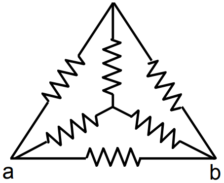
Find the equivalent resistance of the circuits shown in the figure. between the points a and b. Each resistor has resistance r.
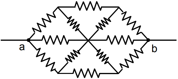
Answer
- $\text{R}_\text{eff}=\frac{\Big(\frac{2\text{r}}{2}\Big)\times\text{r}}{\Big(\frac{2\text{r}}{2}\Big)+\text{r}}$
$=\frac{\text{r}^2}{2\text{r}}=\frac{\text{r}}{2}$
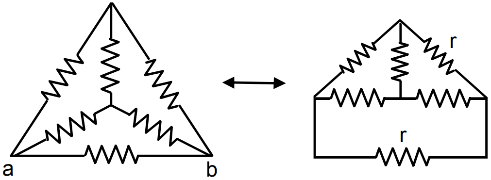
- At 0 current coming to the junction is current going from BO = Current going along OE.
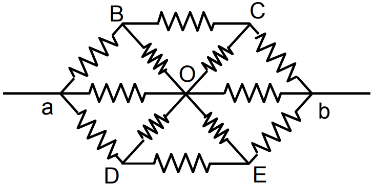
Current on CO = Current on OD
Thus it can be assumed that current coming in OC goes in OB.
Thus the figure becomes
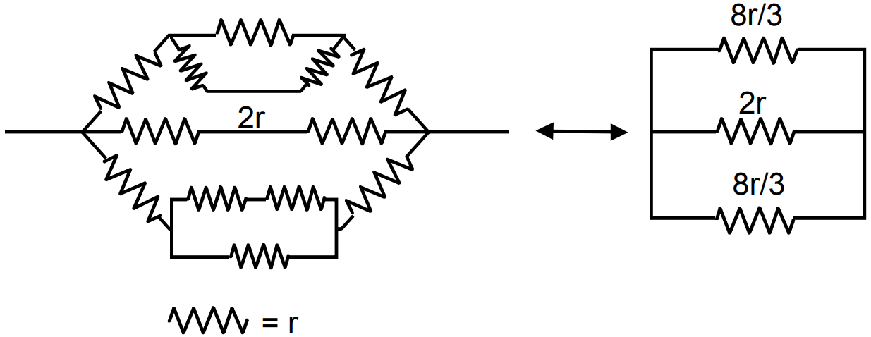
$\Bigg[\text{r}+\Big(\frac{2\text{r}\times\text{r}}{3\text{r}}\Big)+\text{r}\Bigg]=2\text{r}+\frac{2\text{r}}{3}=\frac{8\text{r}}{3}$
$\text{R}_\text{eff}=\frac{\Big(\frac{8\text{r}}{6}\Big)\times2\text{r}}{\Big(\frac{8\text{r}}{6}\Big)+2\text{r}}=\frac{\frac{8\text{r}^2}{3}}{\frac{20\text{r}}{6}}=\frac{8\text{r}^2}{3}\times\frac{6}{20}=\frac{8\text{r}}{10}=4\text{r}.$ View full question & answer→Question 825 Marks
A capacitor of capacitance C is given a charge Q. At t = 0, it is connected to an uncharged capacitor of equal capacitance through a resistance R. Find the charge on the second capacitor as a function of time.
AnswerLet after time t charge on plate B is +Q.
Hence charge on plate A is Q - q.
$\text{V}_\text{A}=\frac{\text{Q}-\text{q}}{\text{C}},\text{V}_\text{B}=\frac{\text{q}}{\text{C}}$
$\text{V}_\text{A}-\text{V}_\text{B}=\frac{\text{Q}-\text{q}}{\text{C}}-\frac{\text{q}}{\text{C}}=\frac{\text{Q}-2\text{q}}{\text{C}}$
Current $=\frac{\text{V}_\text{A}-\text{V}_\text{B}}{\text{R}}=\frac{\text{Q}-2\text{q}}{\text{CR}}$
Current $=\frac{\text{dq}}{\text{dt}}=\frac{\text{Q}-2\text{q}}{\text{CR}}$
$\Rightarrow\frac{\text{dq}}{\text{q}-2\text{q}}=\frac{1}{\text{RC}}\cdot\text{dt}$
$\Rightarrow\int\limits^\text{q}_0\frac{\text{dq}}{\text{Q}-2\text{q}}=\frac{1}{\text{RC}}\cdot\int\limits^\text{t}_0\text{dt}$
$\Rightarrow-\frac{1}{2}\big[\text{In}(\text{Q}-2\text{q})-\text{InQ}\big]=\frac{1}{\text{RC}}\cdot\text{t}$
$\Rightarrow\text{In}\frac{\text{Q}-2\text{q}}{\text{Q}}=\frac{-2}{\text{RC}}\cdot\text{t}$
$\Rightarrow\text{Q}-2\text{q}=\text{Q e}^\frac{-2\text{t}}{\text{RC}}$
$\Rightarrow2\text{q}=\text{Q}\Big(1-\text{e}^\frac{-2\text{t}}{\text{RC}}\Big)$
$\Rightarrow\text{q}=\frac{\text{Q}}{2}\Big(1-\text{e}^\frac{-2\text{t}}{\text{RC}}\Big).$ View full question & answer→Question 835 Marks
The resistance of an iron wire and a copper wire at 20°C are $3.9\Omega$ and $4.1\Omega,$ respectively. At what temperature will the resistance be equal? Temperature coefficient of resistivity for iron is $5.0\times10^{-3}\text{K}^{-1}$ and for copper, it is $4.0\times10^{-3}\text{K}^{-1}.$ Neglect any thermal expansion.
Answer$\text{R}'_\text{Fe}=\text{R}_\text{Fe}(1+\alpha_\text{Fe}\Delta\theta),\text{R}'_\text{Cu}=\text{R}_\text{Cu}(1+\alpha_\text{Cu}\Delta\theta)$
$\text{R}'_\text{Fe}=\text{R}'_\text{Cu}$
$\Rightarrow\text{R}_\text{Fe}(1+\alpha_\text{Fe}\Delta\theta),=\text{R}_\text{Cu}(1+\alpha_\text{Cu}\Delta\theta)$
$\Rightarrow3.9\big[1+5\times10^{-3}(20-\theta)\big]$ $=4.1\big[1+4\times10^{-3}(20-\theta)\big]$
$\Rightarrow3.9+3.9\times5\times10^{-3}(20-\theta)$ $=4.1+4.1\times4\times10^{-3}(20-\theta)$
$\Rightarrow4.1\times4\times10^{-3}(20-\theta)\\-3.9\times5\times10^{-3}(20-\theta)=3.9-4.1$
$\Rightarrow16.4(20-\theta)-19.5(20-\theta)=0.2\times10^3$
$\Rightarrow(20-\theta)(-3.1)=0.2\times10^3$
$\Rightarrow\theta-20=200$
$\Rightarrow\theta=220^\circ\text{C}.$
View full question & answer→Question 845 Marks
A room has AC run for 5 hours a day at a voltage of 220V. The wiring of the room consists of Cu of 1mm radius and a length of 10m. Power consumption per day is 10 commercial units. What fraction of it goes in the joule heating in wires? What would happen if the wiring is made of aluminium of the same dimensions?
$[\rho _{cu} = 1.7 \times 10^{-8}_{Ωm} , \rho _{Al} = 2.7 \times 10^{-8} Ωm]$
AnswerKey concept: The energy dissipated per unit time is the power dissipated $\text{P}=\frac{\Delta\text{W}}{\Delta\text{t}}$ and,
The power across a resistor is $P = I^2R$
Power consumption In a day, i.e., in $5 = 10$units
Or power consumption per hour = 2units
Or power consumption $= 2$units $= 2kW = 2000J/s$
Also, we know that power consumption in resistor,
$P = V × I$
$⇒ 2000W = 220V × I or I ≈ 9A$
Now, the resistance of wire with cross-sectional area A is given by $\text{R}=\rho\frac{\text{I}}{\text{A}}$
Power consumption in first current carrying wire is given by
$P = I^2R$
$\rho\frac{\text{I}}{\text{A}}\text{I}^2=1.7\times10^{-8}\times\frac{10}{\pi\times10^{-6}}\times81\text{J/s}\approx4\text{J/s}$
The fractional loss due to the joule heationg in first wire $=\frac{4}{2000}\times100=0.2\%$
Power loss in Al wire $=4\frac{\rho_\text{Al}}{\rho_\text{Cu}}=1.6\times4=6.4\text{J/s}$
The fractional loss due to the joule heating in second wire $=\frac{6.4}{2000}\times100=0.32\%.$
View full question & answer→Question 855 Marks
In an experiment with a potentiometer, VB = 10V. R is adjusted to be 50Ω (Fig.). A student wanting to measure voltage $E_1$ of a battery (approx. 8V) finds no null point possible. He then diminishes R to 10Ω and is able to locate the null point on the last $(4^{th})$ segment of the potentiometer. Find the resistance of the potentiometer wire and potential drop per unit length across the wire in the second case.
AnswerKey concept: When emf of primary cell is less than the potential difference across the wires of potentiometer, only then the null point is obtained. Equivalent resistance of potentiometer and variable resistor (R = 50Ω) is given by = 50Ω + R' Equivalent voltage applied across potentiometer = 10V
The current through the main circuit, $\text{I}=\frac{\text{V}}{50\Omega+\text{R}'}=\frac{10}{50\Omega+\text{R}'}$ Potential difference across wore of potentiometer, Since with 50Ω resistor, null point is not obtained it is possible only when $\frac{10\times\text{R}'}{50\times\text{R}}<8$
$⇒ 10R' < 400 + 8R' 2R' < 400 or R' < 200Ω$
Similarly with 10Ω resistor, null point is obtained only when$\frac{10\times\text{R}'}{10+\text{R}}>8$
$\Rightarrow\ 2\text{R}'>80$
$\Rightarrow\ \text{R}'>40$
$\frac{10\times\frac{3}{4}\text{R}'}{10+\text{R}'}>8$
$\Rightarrow\ 7.5\text{R}'<80+8\text{R}'$
$\text{R}'>160$
$\Rightarrow\ 160<\text{R}'<200$
Any R' between 160Ω and 200Ω will achieve.
Since, the null point on the last $(4^{th})$ segment of the potentiometer, therefore potential drop across 400cm of wire $> 8V$.
This imply that potential gradient $k × 400cm > 8V$ or $k × 4m > 8V k > 2V/m$
Similarly, potential drop across 300cm wire $< 8V k × 300cm < 8V$ or $k × 3m < 8V$
$\text{k}<2\frac{2}{3}\text{V/m}$
Thus, $2\frac{2}{3}\text{V/m}>\text{k}>2\text{V/m}.$ View full question & answer→Question 865 Marks
Figure. showa a part of an electric circuit. The potentials at the point a, b and c are 30V, 12V and 2V respectively. Find the currents through the three resistors.
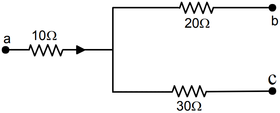
AnswerLet potential at the point be xV
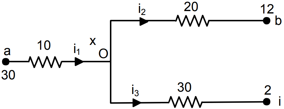
$(30-\text{x})=10\text{i}_1$
$(\text{x}-12)=20\text{i}_2$
$(\text{x}-2)=30\text{i}_3$
$\text{i}_1=\text{i}_2+\text{i}_3$
$\Rightarrow\frac{30-\text{x}}{10}=\frac{\text{x}-12}{20}+\frac{\text{x}-2}{30}$
$\Rightarrow30-\text{x}=\frac{\text{x}-12}{2}+\frac{\text{x}-2}{3}$
$\Rightarrow30-\text{x}=\frac{3\text{x}-36+2\text{x}-4}{6}$
$\Rightarrow180-6\text{x}=5\text{x}-40$
$\Rightarrow11\text{x}=220\Rightarrow\text{x}=\frac{220}{11}=20\text{V}$
$\text{i}_1=\frac{30-20}{10}=1\text{A}$
$\text{i}_2=\frac{20-12}{20}=0.4\text{A}$
$\text{i}_3=\frac{20-2}{30}=\frac{6}{10}=0.6\text{A}$ View full question & answer→Question 875 Marks
A parallel-plate capacitor has plate area $20cm^2$, plate separation 1.0mm and a dielectric slab of dielectric constant 5.0 filling up the space between the plates. This capacitor is joined to a battery of emf 6.0V through a $100\text{k}\Omega$ resistor. Find the energy of the capacitor $8.9\mu\text{s}$ after the connections are made.
Answer$\text{A} = 20\text{cm}^2, \text{d} = 1\text{mm, K} = 5, \text{e} = 6\text{V}$
$\text{R}=100\times10^3\Omega,\text{t}=8.9\times10^{-5}\text{s}$
$\text{C}=\frac{\text{KE}_0\text{A}}{\text{d}}=\frac{5\times8.85\times10^{-12}\times20\times10^{-4}}{1\times10^{-3}}$
$=\frac{10\times8.85\times10^{-3}\times10^{-12}}{10^{-3}}=88.5\times10^{-12}$
$\text{q}=\text{EC}\Big(1-\text{e}^{\frac{-\text{t}}{\text{RC}}}\Big)$
$=6\times88.5\times10^{-12}\Big(1-\text{e}^{\frac{-89\times10^{-6}}{88.5\times10^{-12}\times10^4}}\Big)=530.97$
Energy $=\frac{1}{2}\times\frac{500.97\times530}{88.5\times10^{-12}}$
$=\frac{530.97\times530.97}{88.5\times2}\times10^{12}$
View full question & answer→Question 885 Marks
A capacitor of capacitance $12.0\mu\text{F}$ is connected to a battery of emf 6.00V and internal resistance $1.00\Omega$ through resistanceless leads. $12.0\mu\text{s}$ after the connections are made, what will be (a) the current in the circuit (b) the power delivered by the battery (c) the power dissipated in heat and (d) the rate at which the energy stored in the capacitor is increasing.
Answer
- $\text{C} = 12.0 \mu\text{F} = 12 \times 10^{-6}$
$\text{emf} = 6.00 \text{V, R} = 1\Omega$
$\text{t} = 12 \mu\text{c}, \text{ i} = \text{i}_0 \text{e}^{\frac{-\text{t}}{\text{RC}}}$
$=\frac{\text{CV}}{\text{T}}\times\text{e}^\frac{-\text{t}}{\text{RC}}=\frac{12\times10^{-6}\times6}{12\times10^{-6}}\times\text{e}^{-1}$
$=2.207=2.1\text{A}$
- Power delivered by battery
We known, $\text{V}=\text{V}_0\text{e}^{\frac{-\text{t}}{\text{RC}}}$ (where V and $V_0$ are potential VI)
$\text{VI}=\text{V}_0\text{I}\text{e}^{\frac{-\text{t}}{\text{RC}}}$
$\Rightarrow\text{VI}=\text{V}_0\text{I}\times\text{e}^{-1}=6\times6\times\text{e}^{-1}=13.24\text{W}$
- $\text{U}=\frac{\text{CV}^2}{\text{T}}\Big(\text{e}^{\frac{-\text{t}}{\text{RC}}}\Big)^2$ $\Big[\frac{\text{CV}^2}{\text{T}}$ = energy drawing per unit time$\Big]$
$=\frac{12\times10^{-6}\times36}{12\times10^{-6}}\times\big(\text{e}^{-1}\big)^2=4.872.$ View full question & answer→Question 895 Marks
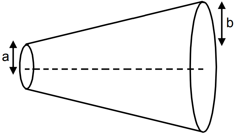
Figure. shows a conductor of length l with a circular cross-section. The radius of the cross-section varies linearly from a to b. The resistivity of the material is ρ. Assuming that b - a << l, find the resistance of the conductor.
AnswerdR, due to the small strip dx at a distanc $\text{x d}=\text{R}=\frac{\text{fdx}}{\pi\text{y}^2}\ ...(1)$
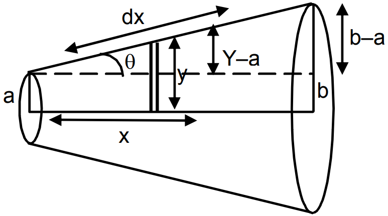
$\tan\theta=\frac{\text{y}-\text{a}}{\text{x}}=\frac{\text{b}-\text{a}}{\text{L}}$
$\Rightarrow\frac{\text{y}-\text{a}}{\text{x}}=\frac{\text{b}-\text{a}}{\text{L}}$
$\Rightarrow\text{L}(\text{y}-\text{a})=\text{x}(\text{b}-\text{a})$
$\Rightarrow\text{Ly}-\text{La}=\text{xb}-\text{xa}$
$\Rightarrow\text{L}\frac{\text{dy}}{\text{dx}}-0=\text{b}-\text{a}\ (\text{diff. w.r.t.x})$
$\Rightarrow\text{L}\frac{\text{dy}}{\text{dx}}=\text{b}-\text{a}$
$\Rightarrow\text{dx}=\frac{\text{Ldy}}{\text{b}-\text{a}}\ ...(2)$
Putting the value of dx in equation (1)
$\text{dR}=\frac{\text{fLdy}}{\pi\text{y}^2(\text{b}-\text{a})}$
$\Rightarrow\text{dR}=\frac{\text{fl}}{\pi(\text{b}-\text{a})}\frac{\text{dy}}{\text{y}^2}$
$\Rightarrow\int\limits^\text{R}_0\text{dR}=\frac{\text{fl}}{\pi(\text{b}-\text{a})}\int\limits^\text{b}_\text{a}\frac{\text{dy}}{\text{y}^2}$
$\Rightarrow\text{R}=\frac{\text{fl}}{\pi(\text{b}-\text{a})}\frac{(\text{b}-\text{a})}{\text{ab}}=\frac{\text{fl}}{\pi\text{ab}}.$ View full question & answer→Question 905 Marks
A capacitor of capacitance $10\mu\text{F}$ is connected to a battery of emf 2V. It is found that it takes 50ms for the charge of the capacitor to become $12.6\mu\text{C}.$ Find the resistance of the circuit.
Answer$\text{C}=10\mu\text{F}=10^{-5}\text{F},\text{emf}=2\text{V}$
$\text{t}=50\text{ms}=5\times10^{-2}\text{s, q}=\text{Q}\Big(1-\text{e}^{\frac{-\text{t}}{\text{RC}}}\Big)$
$\text{Q}=\text{CV}=10^{-5}\times2$
$\text{q}=12.6\times10^{-6}\text{F}$
$\Rightarrow12.6\times10^{-6}=2\times10^{-5}\Big(1-\text{e}^{\frac{-5\times10^{-2}}{\text{R}\times10^{-5}}}\Big)$
$\Rightarrow\frac{12.6\times10^{-6}}{2\times10^{-5}}=1-\text{e}^{\frac{-5\times10^{-2}}{\text{R}\times10^{-5}}}$
$\Rightarrow1-0.63=\text{e}^{\frac{-5\times10^3}{\text{R}}}$
$\Rightarrow\frac{-5000}{\text{R}}=\text{In}\ 0.37$
$\Rightarrow\text{R}=\frac{5000}{0.9942}$
$=5028\Omega=5.028\times10^3\Omega=5\text{K}\Omega.$
View full question & answer→Question 915 Marks
A current of 1.0A exists in a copper wire of cross-section $1.0mm^2$. Assuming one free electron per atom, calculate the drift speed of the free electrons in the wire. The density of copper is $9000kg/m^{-3}.$
Answer$\text{i} = 1\text{A, A} = 1\text{mm}^2 = 1 \times 10^{-6}\text{m}^2$
$\text{f' cu} = 9000\text{kg/m}^3$
Molecular mass has $N_0$ atoms
= mKg has $(N_0/M \times m)$ atoms $=\frac{\text{N}_0\text{Al}9000}{63.5\times10^{-3}}$
No.of atoms = No.of electrons
$\text{n}=\frac{\text{No. of electrons}}{\text{Unit volume}}=\frac{\text{N}_0\text{Af}}{\text{mAl}}=\frac{\text{N}_0\text{f}}{\text{M}}$
$=\frac{6\times10^{23}\times9000}{63.5\times10^{-3}}$
$\text{i}=\text{V}_\text{d}\text{n Ae}.$
$\Rightarrow\text{V}_\text{d}=\frac{\text{i}}{\text{nAe}}=\frac{1}{\frac{6\times10^{23}\times9000}{63.5\times10^{-3}}\times10^{-6}\times1.6\times10^{-19}}$
$=\frac{63.5\times10^{-3}}{6\times10^{23}\times9000\times10^{-6}\times1.6\times10^{-19}}$
$=\frac{63.5\times10^{-3}}{6\times9\times1.6\times10^{26}\times10^{-19}\times10^{-6}}$
$=\frac{63.5\times10^{-3}}{6\times9\times1.6\times10}=\frac{63.5\times10^{-3}}{6\times9\times16}$
$=0.074\times10^{-3}\text{m/s}=0.074\text{mm/ s}.$
View full question & answer→Question 925 Marks
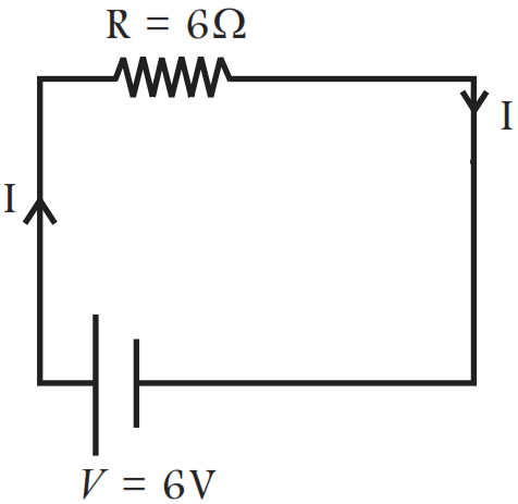
Consider circuit in Fig. How much energy is absorbed by electrons from the initial state of no current (ignore thermal motion) to the state of drift velocity?
AnswerKey concept: Relation between current and drift velocity is given by $I = ne Av_d,$
where vd is the drift speed of electrons and n is the number density of electrons.
According to the Ohm's law current in the circuit
$\text{I}=\frac{\text{V}}{\text{R}}$
$\text{I}=\frac{6\text{V}}{6\Omega}=1\text{A}$
But, $\text{I}=\text{neAv}_\text{d}$
or $\text{v}_\text{d}=\frac{\text{I}}{\text{neA}}$
On substituting the value,
For n = number of electrons/volume $= 10^{29}/m^3$
length of circuit = 10cm, cross-section $= A = (1mm)^2$
$\text{v}_\text{d}=\frac{1}{10^{29}\times16\times10^{-19}\times10^{-6}}$
$=\frac{1}{1.6}\times10^{-4}\text{m/s}$
Therefore, the energy absorbed in the form of KE is given by
Total KE = KE of 1 electron × on. of electrons
$\text{KE}=\frac{1}{2}\text{m}_\text{e}\text{v}_\text{d}^2\times\text{nAl}$
$=\frac{1}{2}\times9.1\times10^{31}\times\frac{1}{2.56}\times10^{-8}\times{10}^{29}\times{10}^{-6}\times10^{-1}$
$=2\times10^{-17}\text{J}$ View full question & answer→Question 935 Marks
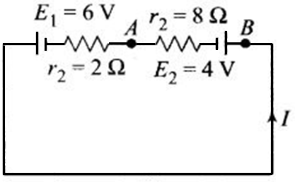
The circuit in Fig. shows two cells connected in opposition to each other. Cell $E_1$ is of emf 6V and internal resistance 2Ω; the cell $E_2$ is of emf 4V and internal resistance 8Ω. Find the potential difference between the points A and B.
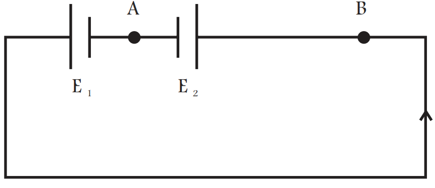
AnswerKey concept: In this problem, after finding the electric current flow in the circuit by using Kirchoff’s law or Ohm’s law, the potential difference across AB can be obtained.
Applying Ohm's law
Equivalent emf of two cells 6 - 4 = 2V and equivalent resistance $=2\Omega+8\Omega=10\Omega$, so the electric current is given by
$\text{I}=\frac{6-4}{2+8}=0.2\text{A}$
Taking loop in anti-clockwise direction, since $E_1 > E_2$
The direction of flow of current is always from high potential to low potential therefore $V_B > V_A$
$\Rightarrow V_B - 4V - (0.2) \times V_A$
Therefore, $V_B - V_A = 3.6V$
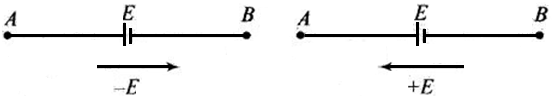
Important Point: Sign convention for the applicaton of Kirchoff's law: For the application of Kirchoff's laws fpllowing sign convention are to be considered.
- The change in potential in traversing a resistance in the direction of current is -iR while in the opposite direction +iR.
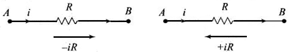
- The change in potential in traversing an emf source from negative to positive terminal is +E while in the opposite direction -E irrespective of the direction of current in the circuit.
View full question & answer→Question 945 Marks
You are given two sets of potentiometer circuits to measure the emf $E_1 $ of a cell. Set A: consists of a potentiometer wire of a material of resistivity $\rho_1$, area of cross-section $A_1$ and length l. Set B: consists of a potentiometer of two composite wire of equal lengths $\frac{\text{l}}2{}$ each, of resistivity $\rho_1,\rho_2$ and area of cross-section $A _1,A_2$ respectively.
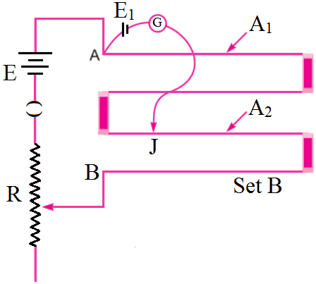
Find the relation between resistivity of the two wires with respect to their area of cross section, if the current flowing in the two sets is same. Compare the balancing length obtained in the two sets. Answer
- $\text{I}=\frac{\varepsilon}{\text{R}+\frac{\rho_1\text{l}}{\text{A}_1}}$ for set A and $\text{I}=\frac{\in}{\text{R}+\frac{\rho_1\text{l}}{2\text{A}_1}+\frac{\rho_2\text{l}}{2\text{A}_2}}\text{for set B}$
Equating the above two expressions, we have,
$\frac{\varepsilon}{\text{R}+\frac{\rho_1\text{l}}{2\text{A}_1}}=\frac{\varepsilon}{\text{R}+\frac{\rho_1\text{l}}{2\text{A}_1}+\frac{\rho_2\text{l}}{2\text{A}_2}}$
$\Rightarrow\text{R}+\frac{\rho_1\text{l}}{\text{A}_1}=\text{R}+\frac{\rho_1\text{l}}{2\text{A}_1}+\frac{\rho_1\text{l}}{2\text{A}_2}$
$\Rightarrow\frac{\rho_1\text{l}}{\text{A}_1}-\frac{\rho_1\text{l}}{2\text{A}_1}=\frac{\rho_2\text{l}}{2\text{A}_2}\dots\text{(i})$
$\Rightarrow\frac{\rho_1}{\text{A}_1}=\frac{\rho_2}{\text{A}_2}$
- Potential gradient of the potentiometer wire for set $\text{A},\text{K}=\text{I}\frac{\rho_1}{\text{A}_1}$
Potential drop across the potentiometer wire in set B
$\text{V}=\text{I}\Big(\frac{\rho_1\text{l}}{2\text{A}_1}+\frac{\rho_2\text{l}}{2\text{A}_2}\Big)\Rightarrow\text{V}=\frac{1}{2}\Big(\frac{\rho_1}{\text{A}_1}+\frac{\rho_2}{\text{A}_2}\Big)\text{I}$
$\text{K}'=\frac{\text{I}}{2}\Big(\frac{\text{r}_1}{\text{A}_1}+\frac{\text{r}_2}{\text{A}_2}\Big),$
Using the condition (i), we get
$\text{K}'=\text{I}\frac{\rho_1}{\text{A}_1},$ which is equal to K.
Therefore, balancing length obtained in the two sets is same. View full question & answer→Question 955 Marks
A capacitor of capacitance C is connected to a battery of emf $\in$ at t = 0 through a resistance R. Find the maximum rate at which energy is stored in the capacitor. When does the rate have this maximum value?
AnswerLet at any time $\text{t},\text{q}=\text{EC}\Big(1-\text{e}^{\frac{-\text{t}}{\text{CR}}}\Big)$
E = Energy stored $=\frac{\text{q}^2}{2\text{c}}=\frac{\text{E}^2\text{C}^2}{2\text{c}}\Big(1-\text{e}^{\frac{-\text{t}}{\text{CR}}}\Big)^2=^{\frac{\text{E}^2\text{C}}{2}}\Big(1-\text{e}^{\frac{-\text{t}}{\text{CR}}}\Big)^2$
R = rate of energy stored $=\frac{\text{q}^2}{2\text{c}}=\frac{-\text{E}^2\text{C}}{2}\Big(\frac{-1}{\text{RC}}\Big)^2\Big(1-\text{e}^{\frac{-\text{t}}{\text{RC}}}\Big)\text{e}^{\frac{-\text{t}}{\text{RC}}}$ $=\frac{\text{E}^2}{\text{CR}}\cdot\text{e}^{\frac{-\text{t}}{\text{RC}}}\Big(1-\text{e}^{\frac{-\text{t}}{\text{CR}}}\Big)$
$\frac{\text{dR}}{\text{dt}}=\frac{\text{E}^2}{2\text{R}}\bigg[\frac{-1}{\text{RC}}\text{e}^{\frac{-\text{t}}{\text{CR}}}.\big(1-\text{e}^{\frac{-\text{t}}{\text{CR}}}\Big)+(-)\cdot\text{e}^{\frac{-\text{t}}{\text{CR}(1-/\text{RC})}}\cdot\text{e}^{\frac{-\text{t}}{\text{CR}}}\bigg]$
$\frac{\text{E}^2}{2\text{R}}=\bigg(\frac{-\text{e}^{\frac{-\text{t}}{\text{CR}}}}{\text{RC}}+\frac{\text{e}^{\frac{-2\text{t}}{\text{CR}}}}{\text{RC}}+\frac{1}{\text{RC}}\cdot\text{e}^{\frac{-2\text{t}}{\text{CR}}}\bigg)$ $=\frac{\text{E}^2}{2\text{R}}\bigg(\frac{2}{\text{RC}}\cdot\text{e}^{\frac{-2\text{t}}{\text{CR}}}-\frac{\text{e}^{\frac{-\text{t}}{\text{CR}}}}{\text{RC}}\bigg)\ ...(1)$
For $\text{R}_\text{max}\frac{\text{dR}}{\text{dt}}=0$
$\Rightarrow2.\text{e}^{\frac{-\text{t}}{\text{RC}}}-1=0\Rightarrow\text{e}^{\frac{-\text{t}}{\text{CR}}}=\frac{1}{2}$
$\Rightarrow\frac{\text{t}}{\text{RC}}=-\text{In}^2\Rightarrow\text{t}=\text{RC In}2$
$\therefore$ Putting t = RC ln 2 in equation (1) We get $\frac{\text{dR}}{\text{dt}}=\frac{\text{E}^2}{4\text{R}}.$
View full question & answer→Question 965 Marks
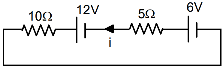
Consider the circuit shown in the figure. Find (a) the current in the circuit (b) the potential drop across the $5\Omega$ resistor (c) the potential drop across the $10\Omega$ resistor. (d) Answer the parts (a), (b) and (c) with reference to the figure.
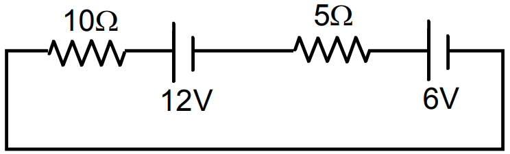
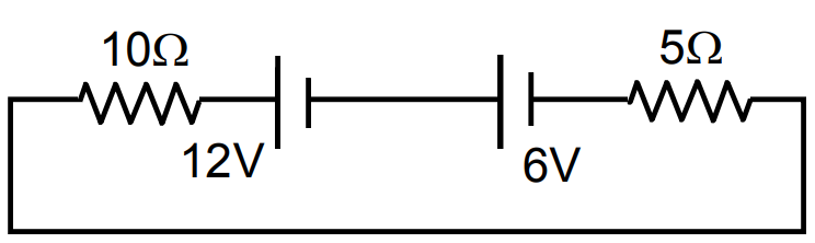
Answer
- Applying Kirchoff’s law,
$10\text{i}-6+5\text{i}-12=0$
$\Rightarrow10\text{i}+5\text{i}=18$
$\Rightarrow15\text{i}=18$
$\Rightarrow\text{i}=\frac{18}{15}=\frac{6}{5}=1.2\text{A}.$
- Potential drop across $5\Omega$ resistor,
$\text{i}5=1.2\times5\text{V}=6\text{V}$
- Potential drop across $10\Omega$ resistor
$\text{i}10=1.2\times10\text{V}=12\text{V}$
- $10\text{i}-6+5\text{i}-12=0$
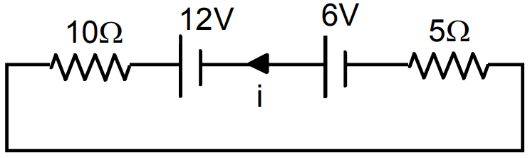
$\Rightarrow10\text{i}+5\text{i}=18$
$15\text{i}=18$
$\Rightarrow\text{i}=\frac{18}{15}=\frac{6}{5}=1.2\text{A}.$
Potential drop across $5\Omega$ resistor = 6V
Potential drop across $10\Omega$ resistor = 12V. View full question & answer→Question 975 Marks
The 2.0Ω resistor shown in the figure is dipped into a calorimeter containing water. The heat capacity of the calorimeter together with water is $2000JK-^1.$
- If the circuit is active for 15 minutes, what would be the rise in the temperature of the water?
- Suppose the 6.0Ω resistor gets burnt. What would be the rise in the temperature of the water in the next 15 minutes?
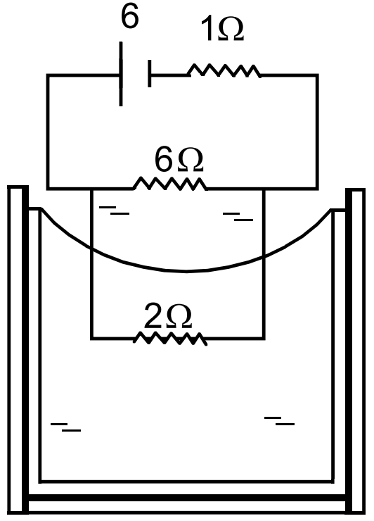
Answer

$\text{R}_\text{eff}=\frac{12}{8}+1=\frac{5}{2}$
$\text{i}=\frac{6}{\frac{5}{2}}=\frac{12}{5}\text{Amp.}$
$\text{i}'6=({\text{i-i}'})2\Rightarrow\text{i}'6=\frac{12}{\frac{5}{2}}\times2-2\text{i}$
$8\text{i}'=\frac{24}{5}\Rightarrow\text{i}'=\frac{24}{5\times8}=\frac{3}{5}\text{Amp}$
$\text{i-i}'=\frac{12}{5}-\frac{3}{5}=\frac{9}{5}\text{Amp}$
- Heat $=\text{i}^2\text{RT}=\frac{9}{5}\times\frac{9}{5}\times2\times15\times60=5832$
$2000J$ of heat raises the temp. by $1K$
$5832J$ of heat raises the temp. by $2.916K.$
- When $6\Omega$ resistor get burnt $\text{R}_\text{eff}=1+2=3\Omega$
$\text{i}=\frac{6}{3}=2\text{Amp}$
Heat $= 2 × 2 × 2 × 15 × 60 = 7200J$
$2000J$ raises the temp. by $1K$
$7200J $ raises the temp by $3.6k.$ View full question & answer→Question 985 Marks
An infinite ladder is constructed with $1\Omega$ and $2\Omega$ resistors, as shown in the figure. (a) Find the effective resistance between the points A and B. (b) Find the current that passes through the $2\Omega$ resistor nearest to the battery.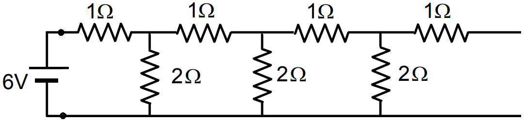
Answer
- Let the equation resistance of the combination be R.
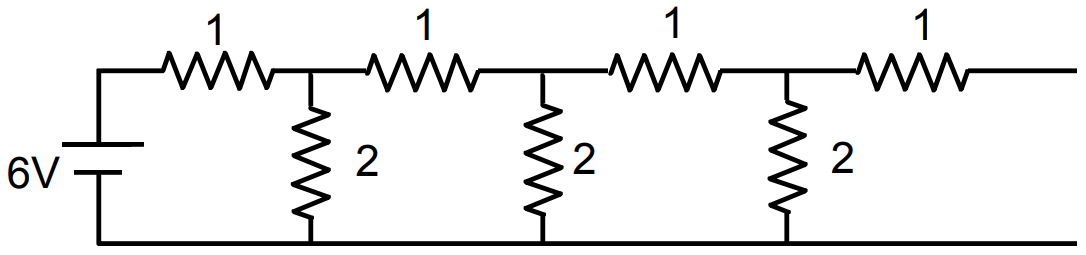
$\Big(\frac{2\text{R}}{\text{R}+2}\Big)+1=\text{R}$
$\Rightarrow\frac{2\text{R}+\text{R}+2}{\text{R}+2}=\text{R}\Rightarrow3\text{R}+2=\text{R}^2+2\text{R}$
$\Rightarrow\text{R}^2-\text{R}-2=0$
$\Rightarrow\text{R}=\frac{+1\pm\sqrt{1+4\times1\times2}}{2.1}$
$=\frac{1\pm\sqrt{9}}{2}=\frac{1\pm3}{2}=2\Omega.$
- Total current sent by battery $=\frac{6}{\text{R}_\text{eff}}=\frac{6}{2}=3$
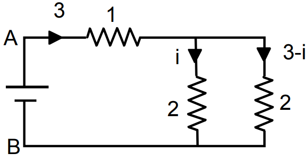
Potential between A and B
$3.1+2\text{i}=6$
$\Rightarrow3+2\text{i}=6\Rightarrow2\text{i}=3$
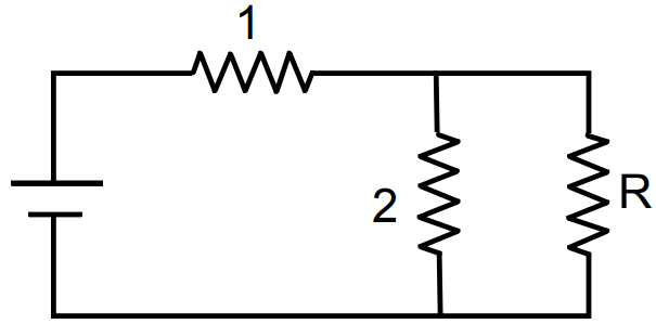
$\Rightarrow\text{i}=1.5\text{a}$ View full question & answer→Question 995 Marks
Let there be n resistors $R_1............R_n$ with $R_{max} = max (R_1......... R_n)$ and $R_{min} = min \{R_1 ..... R_n\}.$
Show that when they are connected in parallel, the resultant resistance $R_P < R_{min}$ and when they are connected in series,
the resultant resistance $R_S > R_{max}.$ Interpret the result physically.
AnswerKey concept: parallel grouping: Same potential difference appeared across each resistance but current distributes in the reverse ratio of thier resistance, i.e. $\text{i}\propto\frac{1}{\text{R}}$.
Series grouping: Same current flows through each resistance but potential difference distributes in the ration of resistance, i.e. $\text{V}\propto\text{R}$.
In parallel combination: When all resistances are connected in parallel, the equivalent resistance $R_p$ is given by
$\frac{1}{\text{R}_\text{p}}=\frac{1}{\text{R}_1}+\ .....\ +\frac{1}{\text{R}_\text{n}}$
On Multiplying both sides by $R_{min},$ we have
$\frac{\text{R}_\text{min}}{\text{R}_\text{p}}=\frac{\text{R}_\text{min}}{\text{R}_1}+\frac{\text{R}_\text{min}}{\text{R}_2}+\ ..... \ +\frac{\text{R}_\text{min}}{\text{R}_\text{n}}$
Here, in RHS, there exist one term $\frac{\text{R}_\text{min}}{\text{R}_\text{min}}=1$ and other terms are positive, so we have
$\frac{\text{R}_\text{min}}{\text{R}_\text{p}}=\frac{\text{R}_\text{min}}{\text{R}_1}+\frac{\text{R}_\text{min}}{\text{R}_2}+\ ..... \ +\frac{\text{R}_\text{min}}{\text{R}_\text{n}}>\text{1}$
This shoews that the resultant resistnce $R_p < R_{min}$
Thus, in parallel combination, the equivalent resistance of resistors even less that the minimum resistance available in combination of resistors.
In series combination: when all resistances are connested in series the equivalent resistance $R_s$ is given by
$R_s = R_1 + .... + R_n$
Here, in RHS, there exist one term having resistance $R_{max}.$
So, we have
or $R_s = R_1 + ..... + R_{max} ..... + ..... + R_n$
$R_s = R_1 + ..... + R_{max} ..... + R_n = R_{max}+ ..... (R_1 + ..... +) R_n$
or $\text{R}_\text{s}\geq\text{R}_\text{max}$
$\text{R}_\text{s}=\text{R}_\text{max}(\text{R}_1+\ ..... +\text{R}_\text{n})$
Thus, in series combination, the equivalent resistance of resistors is greater than the maximum resistance available in combination of resistors.
Physical interpretation:
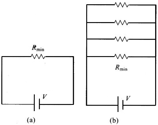
In fig. (b), Rmin provides an equivalent route as in Fig. (a) for current. But in addition there are (n - 1) routes by the remaining (n - 1) resistors. Current in fig. (b) is greater than currenr in Fig. (a). Effective resistance in Fig. (b) < Rmin. Second circuit evidently affords a greater resistance.
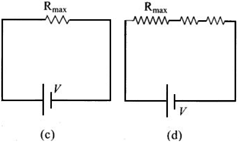
In Fig. (d), Rmax provides an equivalent route as in Fig. (c) for current. Current in Fig. (d) < current In Fig. (c). Effective resistance in Fig. (d) > Rmax. Second circuit affords a greater resistance. View full question & answer→Question 1005 Marks
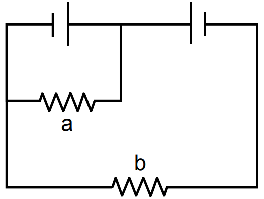
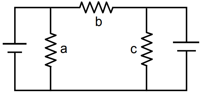
Each of the resistors shown in figure. has a resistance of $10\Omega$ and each of the batteries has an emf of 10V. Find the currents through the resistors a and b in the two circuits.
Answer
- Potential difference between terminals of ‘a’ is 10V.
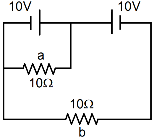
i through $\text{a}=\frac{10}{10}=1\text{A}$
Potential different between terminals of b is 10 - 10 = 0V
i through $\text{b}=\frac{0}{10}=0\text{A}.$
- Potential difference across ‘a’ is 10V
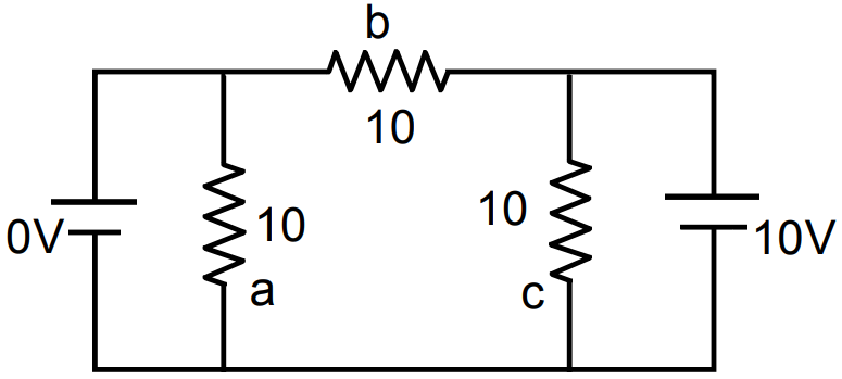
i through $\text{a}=\frac{10}{10}=1\text{A}$
Potential different between terminals of b is 10 - 10 = 0V
i through $\text{b}=\frac{0}{10}=0\text{A}.$ View full question & answer→