Question 15 Marks
Figure shows a potentiometer with a cell of 2.0 V and internal resistance $0.04\ \Omega$ maintaining a potential drop across the resistor wire AB. A standard cell which maintains a constant emf of 1.02 V (for very moderate currents upto a few mA) gives a balance point at 67.3 cm length of the wire. To ensure very low currents drawn from the standard cell, a very high resistance of $600\ \text{k}\Omega$ is put in series with it, which is shorted close to the balance point. The standard cell is then replaced by a cell of unknown emf $\varepsilon$ and the balance point found similarly, turns out to be at 82.3 cm length of the wire.
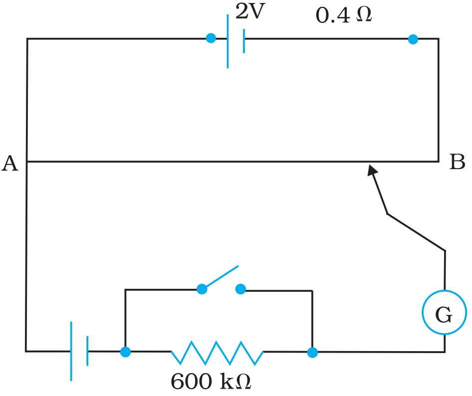
- What is the value $\varepsilon?$
- What purpose does the high resistance of $600\ \text{k}\Omega$ have?
- Is the balance point affected by this high resistance?
- Is the balance point affected by the internal resistance of the driver cell?
- Would the method work in the above situation if the driver cell of the potentiometer had an emf of 1.0 V instead of 2.0 V?
- Would the circuit work well for determining an extremely small emf, say of the order of a few mV (such as the typical emf of a thermo-couple)? If not, how will you modify the circuit?
Answer
- Constant emf of the given standard cell, $E_1 = 1.02\ V$
Balance point on the wire, $l_1 = 67.3\ cm$
A cell of unknown emf, $\varepsilon,$ replaced the standard cell. Therefore, new balance point on the wire, l = 82.3 cm
The relation connecting emf and balance point is,
$\frac{\text{E}_1}{l_1}=\frac{\varepsilon}{l}$
$\varepsilon=\frac{l}{l_1}\times\text{E}_1$
$=\frac{82.3}{67.3}\times1.02=1.247\ \text{V}$.
The value of unknown emf is 1.247 V.
- The purpose of using the high resistance of $600\ \text{k}\Omega$ is to reduce the current through the galvanometer when the movable contact is far from the balance point.
- The balance point is not affected by the presence of high resistance.
- The point is not affected by the internal resistance of the driver cell.
- The method would not work if the driver cell of the potentiometer had an emf of 1.0 V instead of 2.0 V. This is because if the emf of the driver cell of the potentiometer is less than the emf of the other cell, then there would be no balance point on the wire.
- The circuit would not work well for determining an extremely small emf. As the circuit would be unstable, the balance point would be close to end A. Hence, there would be a large percentage of error.
The given circuit can be modified if a series resistance is connected with the wire AB. The potential drop across AB is slightly greater than the emf measured. The percentage error would be small. View full question & answer→Question 25 Marks
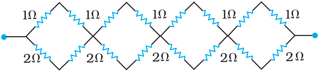
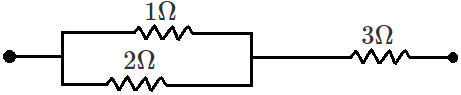
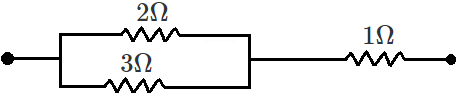
Determine the equivalent resistance of networks shown in Fig.
Answer
- It can be observed from the given circuit that in the first small loop, two resistors of resistance $1\ \Omega$ each are connected in series.
Hence, their equivalent resistance $=(1+1)=2\ \Omega$
It can also be observed that two resistors of resistance $2\ \Omega$ each are connected in series.
Hence, their equivalent resistance $=(2+2)=4\ \Omega$
Therefore, the circuit can be redrawn as
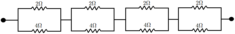
It can be observed that $2\ \Omega\ \text{and}\ 4\ \Omega$ resistors are connected in parallel in all the four loops. Hence, equivalent resistance (R') of each loop is given by,
$\text{R}=\frac{2\times4}{2+4}=\frac{8}{6}=\frac{4}{3}\Omega$
The circuit reduces to,
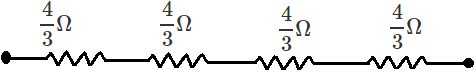
All the four resistors are connected in series.
Hence, equivalent resistance of the given circuit is $\frac{4}{3}\times4=\frac{16}{3}\Omega$
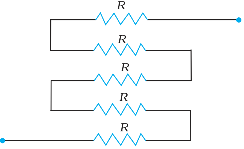
- It can be observed from the given circuit that five resistors of resistance R each are connected in series.
Hence, equivalent resistance of the circuit = R + R + R + R + R
= 5 R View full question & answer→Question 35 Marks
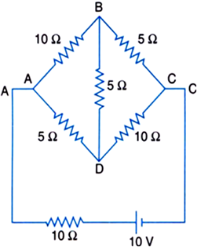
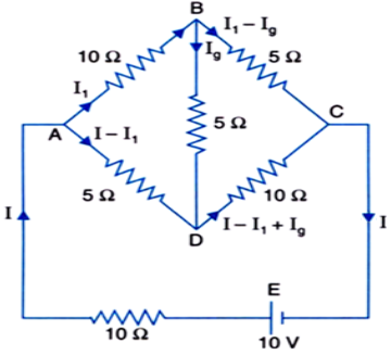
Determine the current in each branch of the network shown in Fig.:
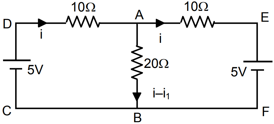
AnswerConsider the mesh ABDA, Now, Applying Kirchhoff's loop rule we get, $-10\text{I}_1-5\text{I}_\text{g}+(\text{I}-\text{I}_1)5=0$ $\Rightarrow\ \ 3\text{I}_1-\text{I}+\text{I}_\text{g}=0\ \ ...\text{(i)}$
Consider the mesh BDCB, Again, applying Kirchhoff's loop rule we get,
$-5\text{I}_\text{g}-10(1-\text{I}_\text{l}+\text{I}_\text{g})+5(\text{I}_\text{I}-\text{I}_\text{g})=0$
$\Rightarrow\ \ 3\text{I}_1-2\text{I}-4\text{I}_\text{g}=0\ \ ...\text{(ii)}$
Applying Kirchhoff's loop rule to the mesh ABCEA, $-10\text{I}_1-5(\text{I}_1-\text{I}_\text{g})-10\text{I}+10=0$$\text{or}\ \ 3\text{I}_1+2\text{I}-\text{I}_\text{g}=2\ \ ...{(\text{iii})}$
Equations (i), (ii) and (iii) are simultaneous equations. On solving these equations,
we will find the unknown values of current.
Adding (i) and (iii), we get $6\text{I}_\text{1}+\text{I}=2\ \ ...(\text{iv})$ Multiplying (i) by 4 and adding in (ii),
we get $15\text{I}_\text{1}-6\text{I}0=0\ \ ...\text{(v)}$
Solving equations (iv) and (v), we get $\text{I}_1=\frac{4}{17}\text{A}=0.235\ \text{A}$
So, current in branch AB is 0.235 A.
Putting the value of $I_1$ in equation (v) and simplifying,
we get Total current, $\text{I}=\frac{10}{17}=0.588\ \text{A}$
Putting the values of I and $ I_1$ in equation (iii) and simplifying,
we get $\text{I}_\text{g}=\frac{2}{17}\text{A}=-0.118\ \text{A}$
The negative sign indicates that the direction of current is opposite to that shown in Fig.
above. So, current in branch BD is -0.118 A.
Current in branch BC is $(\text{I}_1-\text{I}_\text{g})\text{i.e}.,\frac{4}{17}-\Big(-\frac{2}{17}\Big)$
$\text{i.e.,}\frac{6}{17}\ \text{or}\ 0.353\ \text{A}.$
Current in branch AD is $(I - I_1)$
$\text{i.e.,}\Big(\frac{10}{17}-\frac{4}{17}\Big)\text{A i.e.,}\ \frac{6}{17}\text{A or}\ 0.353\ \text{A}$
Current in branch DC is $(I_1 - I_1 + I_g)$
$\text{i.e.,}\frac{6}{17}+\Big(-\frac{2}{17}\Big)\text{A or}\ \frac{4}{17}\text{A or}\ 0.235\ \text{A}.$ View full question & answer→Question 45 Marks
Two wires of equal length, one of aluminium and the other of copper have the same resistance. Which of the two wires is lighter? Hence explain why aluminium wires are preferred for overhead power cables.
$(\rho_{\text{A}1}=2.63\times10^{-8}\Omega\ \text{m,}\ \text{Relative density of Al}=2.7,\ \text{of Cu}=8.9)$
AnswerResistivity of alurruniurn, $\rho_{\text{Al}}=2.63\times10^{-8}\Omega\ \text{m}$
Relative density of aluminium, $d_1 = 2.7$
Let $l_1$ be the length of aluminium wire and $m_1$, be its mass.
Resistance of the aluminium wire =$ R_1$
Area of cross-section of the aluminium wire $= A_1$
Resistivity of copper, $\rho_{\text{Cu}}=1.72\times10^{-8}\Omega\ \text{m}$
Relative density of copper, $d_2 = 8.9$
Let $l_2$ be the length of copper wire and $m_2$ be its mass.
Resistance of the copper wire $= R_2$
Area of cross-section of the copper wire $= A_2$
The two relations can be written as
$\text{R}_1=\rho_1\frac{l_1}{\text{A}_1}\ \ ...(1)$
$\text{R}_2=\rho_2\frac{l_2}{\text{A}_2}\ \ ...(2)$
It is given that,
$\text{R}_1=\text{R}_2$
$\rho_1\frac{l_1}{\text{A}_1}=\rho_2\frac{l_2}{\text{A}_2}$
and,
$l_1=l_2$
$\therefore\ \frac{\rho_1}{\text{A}_1}=\frac{\rho_2}{\text{A}_2}$
$\frac{\text{A}_1}{\text{A}_2}=\frac{\rho_1}{\rho_2}$
$=\frac{2.63\times10^{-8}}{1.72\times10^{-8}}=\frac{2.63}{1.72}$
Mass of the aluminium wire,
$m_1 =$ volume \times Density
$=\text{A}_1l_1\times\text{d}_1=\text{A}_1\ l_1\text{d}_1\ \ ...(3)$
Mass of the copper wire,
$m_2 =$ volume \times Density
$=\text{A}_2l_2\times\text{d}_2=\text{A}_2\ l_2\text{d}_2\ \ ...(4)$
Dividing equation (3) by equation (4), we obtain
$\frac{\text{m}_1}{\text{m}_2}=\frac{\text{A}_1l_1\text{d}_1}{\text{A}_2l_2\text{d}_2}$
$\text{For}\ l_1=l_2,$
$\frac{\text{m}_1}{\text{m}_2}=\frac{\text{A}_1\text{d}_1}{\text{A}_ 2\text{d}_2}$
$\text{For}\ \frac{\text{A}_1}{\text{A}_2}=\frac{2.63}{1.72},$
$\frac{\text{m}_1}{\text{m}_2}=\frac{2.63}{1.72}\times\frac{2.7}{8.9}=0.46$
It can be inferred from this ratio that $m_1$ is less than $m_2$ Hence, aluminium is lighter than copper.
Since aluminium is lighter, it is preferred for overhead power cables over copper.
View full question & answer→Question 55 Marks
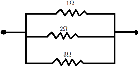
Given the resistances of $1\ \Omega,\ 2\ \Omega,\ 3\ \Omega,$ how will be combine them to get an equivalent resistance of,
- $(11/3)\ \Omega$
- $(11/5)\ \Omega$
- $6\ \Omega$
- $(6/11)\ \Omega?$
AnswerThe resistance of the given resistors is, $\text{R}_1=1\ \Omega,\ \text{R}_2=2\ \Omega,\ \text{R}_3=3\ \Omega\ 2,$
- Equivalent resistance, $\text{R}=\frac{11}{3}\Omega$
Consider the followinq combination of the resistors.
 Equivalent resistance of the circuit is given by,
$\text{R}=\frac{2\times1}{2+1}+3=\frac{2}{3}+3=\frac{11}{3}\Omega$
- Equivalent resistance, $\text{R}=\frac{11}{5}\Omega$
Consider the following combtnatlon of the resistors.
 Equivalent resistance of the circuit is given by,
$\text{R}=\frac{2\times3}{2+3}+1=\frac{6}{5}+1=\frac{11}{5}\Omega$
- Equivalent resistance, $\text{R}=6\ \Omega$
Consider the series combination of the resistors, as shown in the given circuit.

Equivalent resistance of the circuit is given by the sum.
$\text{R}=1+2+3=6\ \Omega$
- Equivalent resistance, $\text{R}=\frac{6}{11}\Omega$
Consider the series combination of the resistors, as shown in the given circuit.
Equivalent resistance of the circuit is given by,
$\text{R}=\frac{1\times2\times3}{1\times2+2\times3+3\times1}=\frac{6}{11}\Omega$ View full question & answer→Question 65 Marks
- Plot a graph showing variation of voltage vs the current drawn from the cell. How can one get information from this plot about the emf of the cell and its internal resistance?
- Two cells of emf’s $E_1$ and $E_2$ and internal resistance $r_1$ and $r_2$ are connected in parallel. Obtain the expression for the emf and internal resistance of a single equivalent cell that can replace this combination?
Answer
-
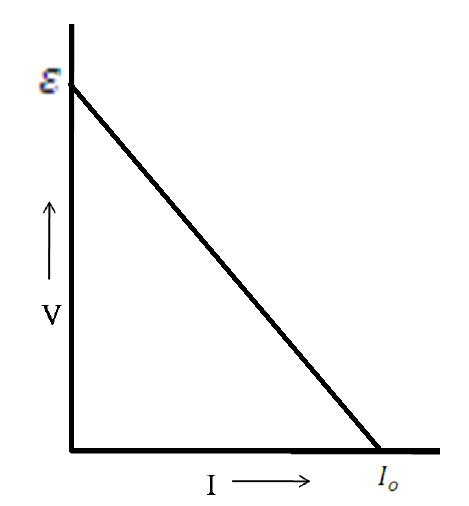
$V=\varepsilon-Ir$
When current is zero (I = 0), $\text{V}=\in$
And when V = 0, $\text{I}=\text{I}_0,\text{ }r=\frac{\in}{I_0}$
-
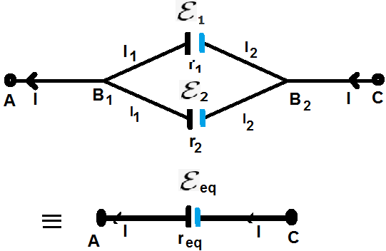
$\text{V}=\text{V}(\text{B}_1)-\text{V}(\text{B}_2)=\varepsilon_1-I_1r_1$
$\text{V}=\text{V}(\text{B}_1)-\text{V}(\text{B}_2)=\varepsilon_2-I_2r_2$
$I=I_1+I_2$
$=\frac{\varepsilon_1-\text{V}}{r_1}+\frac{\varepsilon_2-\text{V}}{r_2}=\Big(\frac{\varepsilon_1}{r_1}+\frac{\varepsilon_2}{r_2}\Big)-\text{V}\Big(\frac{1}{r_1}+\frac{1}{r_2}\Big)$
$\text{V}=\frac{\varepsilon_1r_2+\varepsilon_2r_1}{r_1+r_2}-I\frac{r_1r_2}{r_1+r_2}$
On comparing with
$\text{V}=\varepsilon_{eq}-Ir_{eq}$
we get
$\varepsilon_{eq}=\frac{\varepsilon_1r_2+\varepsilon_2r_1}{r_1+r_2}$
$r_{eq}=\frac{r_1r_2}{r_1+r_2}$
Alternate Answer
A student may write the last two results in the following form.
$\frac{1}{r_{eq}}=\frac{1}{r_1}+\frac{1}{r_2}$
$\frac{\varepsilon_{eq}}{r_{eq}}=\frac{\varepsilon_1}{r_1}+\frac{\varepsilon_2}{r_2}$ View full question & answer→Question 75 Marks
-
- State the principle on which a potentiometer works. How can a given potentiometer be made more sensitive?
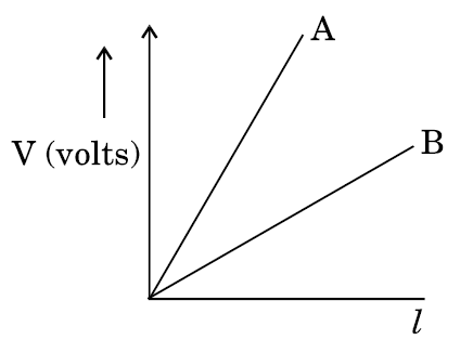
- In the graph shown below for two potentiometers, state with reason which of the two potentiometers, A or B, is more sensitive.
- Two metallic wires, $P_1$ and $P_2$ of the same material and same length but different cross-sectional areas, $A_1$ and $A_2$ are joined together and connected to a source of emf. Find the ratio of the drift velocities of free electrons in the two wires when they are connected (i) in series, and (ii) in parallel.
Answer
-
- The potential difference across any length of wire is directly proportional to the length provided current and area of cross section are constant i.e., ? ? = ?? where ? is the potential drop per unit length.
It can be made more sensitive by decreasing current in the main circuit/decreasing potential gradient/increasing resistance put in series with the potentiometer wire.
- Potentiometer B
Has smaller value of $\text{ }^V/_l$ (slope/potential gradient).
- In series, the current remains the same.
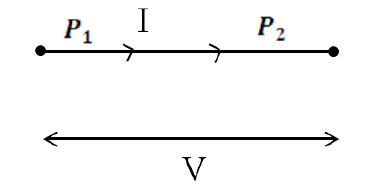
$I=neA_1V_{d1}=neA_2V_{d2}$
$\therefore\frac{V_{d1}}{V_{d2}}=\frac{A_2}{A_1}$
In parallel potential difference is same but currents are different.
$V=I_1R_1=neA_1V_{d1}\frac{\rho l}{A_1}=ne\rho V_{d1}l$
Similarly, $V=I_2R_2=ne\rho V_{d2}l$
$I_1R_1=I_2R_2$
$\therefore\frac{V_{d1}}{V_{d2}}=1$ View full question & answer→Question 85 Marks
- In the circuit diagram given below, AB is a uniform wire of resistance 15Ω and length 1 m. It is connected to a cell $E_1$ of emf 2V and negligible internal resistance and a resistance R. The balance point with another cell $E_2$ of emf 75 mV is found at 30 cm from end A. Calculate the value of R.
- Why is potentiometer preferred over a voltmeter for comparison of emf. of cells?
- Draw a circuit diagram to determine internal resistance of a cell in the laboratory.
Answer
- Current through AB
$I=\frac{\varepsilon_1}{R+R_{AB}}=\frac{2}{R+15}$
P.D. across AB, $V_{AB}=IR_{AB}=\big(\frac{2}{R+15}\big).15$
Potential gradient $k=\frac{V_{AB}}{AB}=\frac{30}{(R+15)\times100}=\frac{0.3}{R+15}$
Balance length for cell $E_2 (= 75mV), l=\frac{E_2}{k}$
$\Rightarrow30=\frac{75\times10^{-3}(R+15)}{0.3}$
$\Rightarrow\frac{9\times10^3}{75}=R+15$
$\Rightarrow R=105\Omega$
- A potentiometer is preferred over a voltmeter because potentiometer does not draw current for any measurement unlike a voltmeter.
(Alternatively, Potentiometer compares the emf values while the voltmeter would only compare the terminal p.d.’s of the two cells.)
-
View full question & answer→Question 95 Marks
- Derive an expression for drift velocity of electrons in a conductor. Hence, deduce Ohm's law.
- A wire whose cross-sectional area is increasing linearly from its one end to the other, is connected across a battery of V volts.
Which of the following quantities remain constant in the wire?
- Drift speed.
- Current density.
- Electric current.
- Electric field.
Answer
- Let an electric field E be applied the conductor. Acceleration of each electron is
$a=-\frac{eE}{m}$
Velocity gained by the electron
$v=-\frac{eE}{m}t$
Let the conductor contain n electrons per unit volume. The average value of time $'t'$, between their successive collisions, is the relaxation time,$'\tau'$.
Hence average drift velocity $v_d=\frac{-eE}{m}\tau$
The amount of charge, crossing area A, in time $\triangle t$, is
$\equiv neAv_d\triangle t=I\triangle t$
Substituting the value of $v_d$, we get
$I\triangle t=neA\bigg(\frac{eE\tau}{m}\bigg)\triangle t$
$\therefore\text{ }I=\bigg(\frac{e^2A\tau n}{m}\bigg)E=\sigma E,\bigg(\sigma=\frac{e^2\tau n}{m} \text{is the conductivity}\bigg)$
But I = JA, where J is the current density
$\Rightarrow\text{J}=\big(\frac{e^2\tau n}{m}\big)E$
$\Rightarrow\text{J}=\sigma E$
This is Ohm’s law
- Electric current well remain constant in the wire. All other quantities, depend on the cross sectional area of the wire.
View full question & answer→Question 105 Marks
- Define the term drift velocity.
- On the basis of electron drift, derive an expression for resistivity of a conductor in terms of number density of free electrons and relaxation time. On what factors does resistivity of a conductor depend?
- Why alloys like constantan and manganin are used for making standard resistors?
Answer
- Average velocity acquired by the electrons in the conductor in the presence of external electric field.
Alternate Answer
$[\text{V}_{d} =\frac{-eE\tau}{\text{m}}$ where $\tau$is the relaxation time.]
- $\text{V}_{d} =\frac{-eE\tau}{\text{m}}$
We have $\text{E} = - \frac{\text{V}}{\ell'}$
where V is potential difference across the length $\ell$
of the conductor
$\text{V}_{d} = \frac{\text{eV}\tau}{\text{m}\ell}$ Current flowing $I = neAv_d$
I = neA$\text{V}_{d}\frac{\text{eV}\tau}{\text{ml}} = \frac{ne^{2}\text{AV}\tau}{\text{ml}}$
$\frac{\text{I}}{\text{V}} = \frac{\text{ne}^{2}A\tau}{ml} = \frac{1}{\text{R}}$ . . . . . (i)
Also, $\text{R} = \rho\frac{\ell}{\text{A}}$ . . . . (ii)
Comparing (i) and (ii)
$\rho = \frac{m}{ne^{2}\tau}$
Resistivity of the material of a conductor depends on the relaxation time, i.e., temperature and the number density of electrons.
- Because constantan and manganin show very weak dependence of resistivity on temperature.
View full question & answer→Question 115 Marks
- State the principle of working of a potentiometer.
- In the following potentiometer circuit, AB is a uniform wire of length 1 m and resistance 10Ω. Calculate the potential gradient along the wire and balance length AO ( = l).
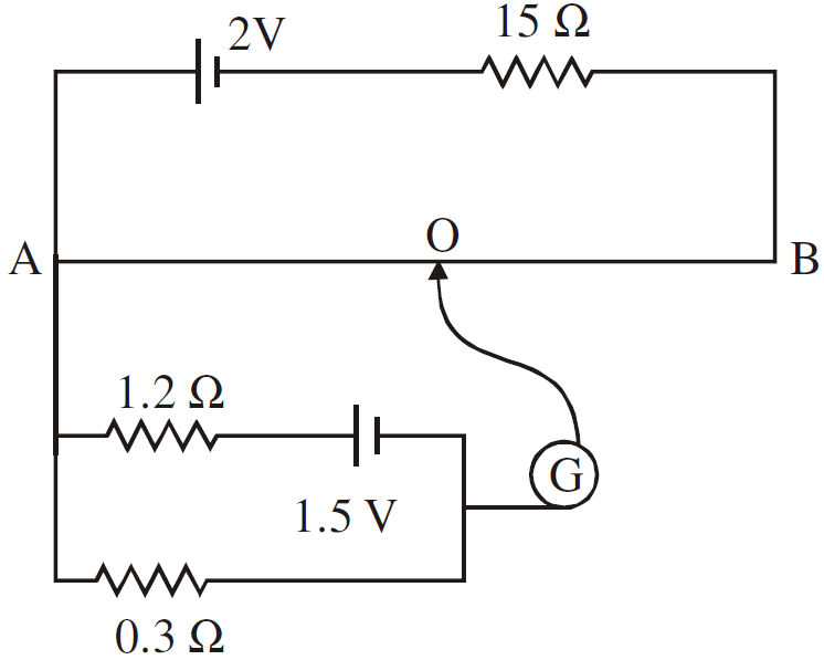
AnswerWhen constant current flows through a conductor of uniform area of cross section, the potential difference, across a length l of the wire, is directly proportional to that length of the wire.
$[ \text{V}\propto{l}$ (Provided current and area are constant)]
Current flowing in the potentiometer wire -
$ i = \frac{\text{E}}{\text{R}_{total}} = \frac{2.0}{15 + 10} = \frac{2}{25}\text{A}$
$\therefore$ Potential difference across the two ends of the wire
$\text{V}_{AB} = \frac{2}{25}\times10\text{V} = \frac{20}{25} = 0.8\text{volt}$
Hence potential gradient $\text{K} = \frac{\text{V}_{AB}}{l_AB} = \frac{0.8}{1.0} = 0.8\text{V/m}$
Current flowing in the circuit containing experimental cell,
$\frac{1.5}{1.2 + 0.3}1\text{A}$
Hence, potential difference across length AO of the wire
$ = 0.3\times1\text{V} = 0.3\text{V}$
$\Rightarrow 0.3 = \text{K}\times l _{AO}$
$ = 0.8 \times l _{AO}$
$\Rightarrow l_{AO} = \frac{0.3}{0.8}\text{m} = 0.375 \text{m}$
$ = 37.5 \text{cm}$.
View full question & answer→Question 125 Marks
- State the two Kirchhoff's laws. Explain briefly how these rules are justified.
- The current is drawn from a cell of emf E and internal resistance r connected to the network of resistors each of resistance r as shown in the figure. Obtain the expression for (i) the current draw from the cell and (ii) the power consumed in the network.
Answer
- Junction Rule: At any Junction, the sum of currents, entering the junction, is equal to the sum of currents leaving the junction.
Loop Rule: The Algebraic sum, of changes in potential, around any closed loop involving resistors and cells, in the loop is zero.
$\sum(\triangle V)=0$
Justification: The first law is in accord with the law of conservation of charge.
The Second law is in accord with the law of conservation of energy.
- Equivalent resistance of the loop
$\text{R}=\frac{r}{3}$
Hence current drawn from the cell
$\text{I}=\frac{E}{\frac{r}{3}+r}=\frac{3E}{4r}$
Power consumed $\text{P}=I^2(\frac{r}{3})$
$=\frac{9E^2}{16r^2}\times\frac{4r}{3}=\frac{3E^2}{4r}$ View full question & answer→Question 135 Marks
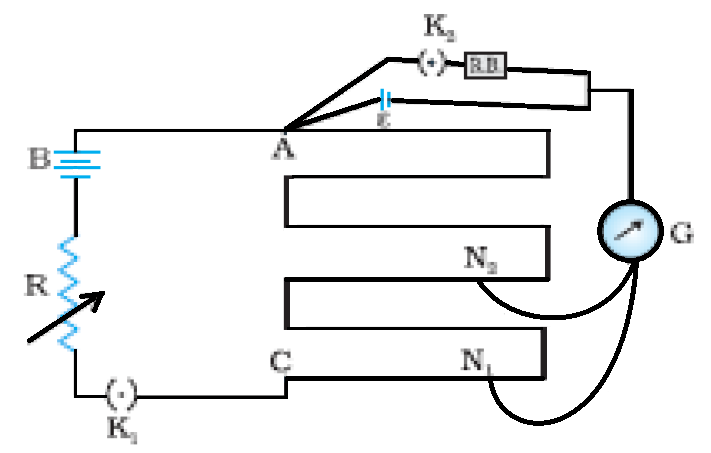
- State the working principle of a potentiometer. With the help of the circuit diagram, explain how a potentiometer is used to compare the emf’s of two primary cells. Obtain the required expression used for comparing the emfs.
- Write two possible causes for one sided deflection in a potentiometer experiment.
Answer
- Working Principle of Potentiometer:
Principle. Consider a long resistance wire AB of uniform cross-section. Its one end A is connected to the positive terminal of battery $B_1$ whose negative terminal is connected to the other end B of the wire through key K and a rheostat (Rh). The battery $B_1$ connected in circuit is called the driver battery and this circuit is called the primary circuit. By the help of this circuit a definite potential difference is applied across the wire AB; the potential falls continuously along the wire from A to B. The fall of potential per unit length of wire is called the potential gradient. It is denoted by ‘k’. A cell e is connected such that its positive terminal is connected to end A and the negative terminal to a jockey J through the galvanometer G. This circuit is called the secondary circuit.
In primary circuit the rheostat (Rh) is so adjusted that the deflection in galvanometer is on one side when jockey is touched on wire at point A and on the other side when jockey is touched on wire at point B.
The jockey is moved and touched to the potentiometer wire and the position is found where galvanometer gives no deflection. Such a point P is called null deflection point.
$V_{AB}$ is the potential difference between points A and B and L metre be the length of wire, then the potential gradient
$\text{k} =\frac{\text{V}_{AB}}{\text{L}}$
If the length of wire AP in the null deflection position be l, then the potential difference between points A and P,
$V_{AP} = kl$
$\therefore\text{The emf of cell,}\varepsilon =\text{V}_{AP} = kl$
In this way the emf of a cell may be determined by a potentiometer.
Comparison of emf’s of two cells: First of all the ends of potentiometer are connected to a battery $B_1,$ key K and rheostat Rh such that the positive terminal of battery $B_1$ is connected to end A of the wire. This completes the primary circuit. Now the positive terminals of the cells $C_1$ and $C_2$ whose emfs are to be compared are connected to A and the negative terminals to the jockey J through a two-way key and a galvanometer (fig). This is the secondary circuit.
Method:
- By closing key K, a potential difference is established and rheostat is so adjusted that when jockey J is made to touch at ends A and B of wire, the deflection in galvanometer is on both sides. Suppose in this position the potential gradient is k.
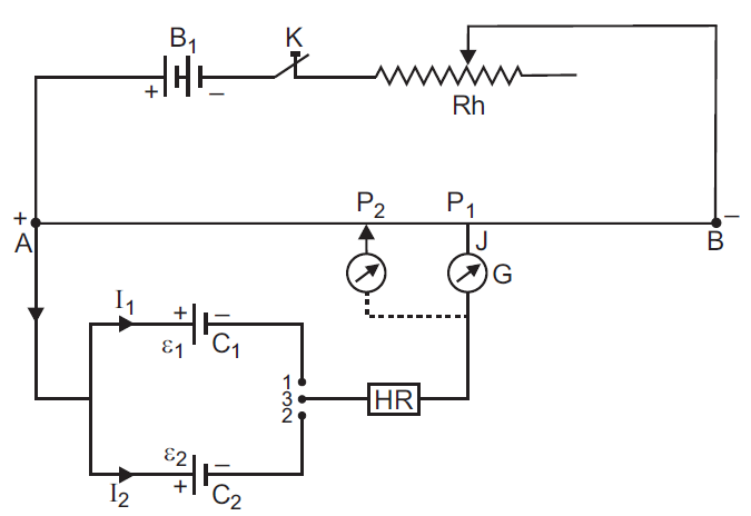
- Now plug is inserted between the terminals 1 and 3 so that cell $C_1$ is included in the secondary circuit and jockey J is slided on the wire at $P_1$ (say) to obtain the null point. The distance of $P_1$ from A is measured. Suppose this length is $l_1$ i. e. $AP_1 =l_1$
$\therefore\text{The emf of cell C}_{1},\varepsilon = kl_{1}$ - - - - -(i)
- Now plug is taken off between the terminals 1 and 3 and inserted in between the terminals 2 and 3 to bring cell $C_2$ in the circuit. Jockey is slided on wire and null deflection position $P_2$ is noted. Suppose distance of $P_2$ from A is $l_2$ i. e. $AP_2 =l_2$
$\therefore\text{The emf of cell C}_{2},\varepsilon_{2} = kl_{2}$ - - - - - -- (ii)
Dividing (i) by (ii), we get
$\frac{\varepsilon_{1}}{\varepsilon_{2}} = \frac{l_{1}}{l_{2}}$ - - - - - - - - -(iii)
Thus emf’s of cells may be compared. Out of these cells if one is standard cell, then the emf of other cell may be calculated.
- Possible causes for one side deflection:
- If emf $\varepsilon_{1}$(or $\varepsilon_{2}$ ) is more than the emf driver cell (auxiliary battery), then we have one sided deflection.
- when the positive end of the potentiometer wire is connected to negative terminal of the cell whose emf is to be determined.
View full question & answer→Question 145 Marks
- State Kirchhoff’s rules for an electric network. Using Kirchhoff’s rules, obtain the balance condition in terms of the resistances of four arms of Wheat sone bridge.
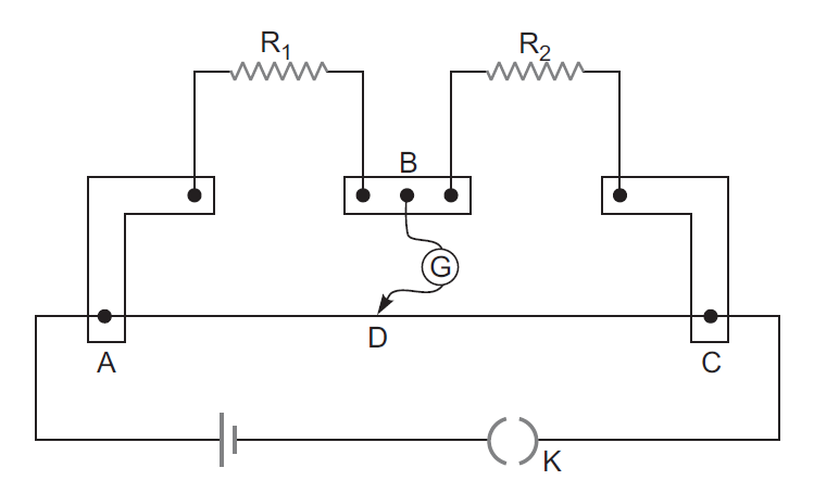
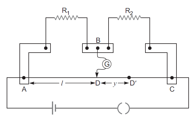
- In the meter bridge experimental set up, shown in the figure, the null point ‘D’ is obtained at a distance of 40 cm from end A ofthe meter bridge wire. If a resistance of 10 Ω is connected in series with $R_1$, null point is obtained at AD = 60 cm. Calculate the value of $R_1$ and $R_2.$

Answer
- Kirchhoff’s Rule
- At any junction, the sum of the currents entering the junction is equal to the sum of the currents leaving the junction.
- The algebraic sum of the charges in potential around any closed loop involving resistors and cells in the loop is zero.
Condition of balance of a Wheatstone bridge: The circuit diagram of Wheatstone bridge is shown in fig.
P, Q, R and S are four resistance forming a closed bridge, called Wheatstone bridge. A battery is connected across A and C, while a galvanometer is connected between B and D. At balance, there is no current in galvanometer.
Derivation of Formula: Let the current given by battery in the balanced position be I. This current on reaching point A is divided into two parts $I_1$ and $I_2$ . As there is no current in galvanometer in balanced state, current in resistances P and Q is $I_1$ and in resistances R and S it is $I_2 .$
Applying Kirchhoff’s I law at point A
$I - I_1 - I_2 = 0$ or $I = I_1 + I_2 - - - - - - - - (i)$
Applying Kirchhoff’s II law to closed mesh ABDA
$- I_1P + I_2R = 0$ or $I_1P = I_2 R - - - - - - - (ii)$
Applying Kirchhoff’s II law to mesh BCDB
$- I_1Q + I_2S = 0$ or $I_1Q = I_2S - - - - -- - (iii)$
Dividing equation (ii) by (iii), we get
$\frac{\text{I}_{1}\text{P}}{\text{I}_{1}\text{Q}} = \frac{\text{I}_{2}\text{R}}{\text{I}_{2}\text{S}}\text{ or }\frac{\text{P}}{\text{Q}} = \frac{\text{R}}{\text{S}}$ - - - - - - -(iv)
This is the condition of balance of Wheatstone bridge.
-
For null point at D, balance length $\ell_{1}$ = 40 cm
So, $\frac{\text{R}_{1}}{\text{R}_{2}} = \frac{\text{AD}}{\text{DC}} =\frac{40}{(100- 40)} = \frac{2}{3}$ - - - -- - (i)
If resistance 10 $\Omega$ is connected in series of $R_1$, then balance length AD' > AD i.e. balance point shifts by length ‘y’ towards C i.e., AD = 60 cm.
$\frac{\text{R}_{1} + 10}{\text{R}_{2}} = \frac{\text{AD}"}{\text{D}'\text{C}} = \frac{60}{100-60} = \frac{3}{2}$
$\frac{\text{R}_{1}}{\text{R}_{2}} + \frac{10}{\text{R}_{2}} =\frac{3}{2}$- - - - - -- -- - -(ii)
From equations (1) and (2), we have
$\frac{2}{3} +\frac{10}{\text{R}_{2}} =\frac{3}{2}$
$\frac{10}{\text{R}_{2}} = \frac{3}{2} - \frac{2}{3} =\frac{9-4}{6} = \frac{5}{6}$
$\Rightarrow\text{R}_{2} = \frac{ 10\times6}{5} = 12\text{ ohm}$
From equation (1), we have
$\frac{\text{R}_{1}}{12} = \frac{2}{3}\Rightarrow\text{R}_{1} = \frac{12\times2}{3} =8\text{ ohm}.$ View full question & answer→Question 155 Marks
How many time constants will elapse before the energy stored in the capacitor reaches half of its equilibrium value in a charging RC circuit?
Answer$\text{q}=\text{Q}\big(1-\text{e}^{-\text{n}}\big)$
$\frac{1}{2}\frac{\text{Q}^2}{\text{C}}$ = Initial value; $\frac{1}{2}\frac{\text{q}^2}{\text{c}}$ = Final value
$\frac{1}{2}\frac{\text{q}^2}{\text{c}}\times2=\frac{1}{2}\frac{\text{Q}^2}{\text{C}}$
$\Rightarrow\text{q}^2=\frac{\text{Q}^2}{2}\Rightarrow\text{q}=\frac{\text{Q}}{\sqrt{2}}$
$\frac{\text{Q}}{\sqrt{2}}=\text{Q}(1-\text{e}^{\text{n}})$
$\Rightarrow\frac{1}{\sqrt{2}}=1-\text{e}^{-\text{n}}\Rightarrow\text{e}^{-\text{n}}=1-\frac{1}{\sqrt{2}}$
$\Rightarrow\text{n}=\log\Big(\frac{\sqrt{2}}{\sqrt{2}-1}\Big)=1.22$
View full question & answer→Question 165 Marks
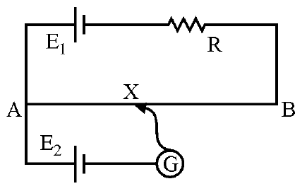
While doing an experiment with potentiometer (Fig.) it was found that the deflection is one sided and (i) the deflection decreased while moving from one end A of the wire to the end B; (ii) the deflection increased. while the jockey was moved towards the end B.
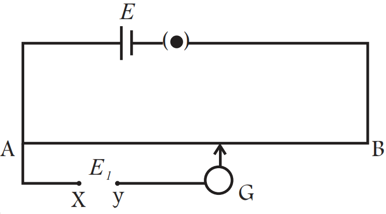
- Which terminal +or -ve of the cell $E_1,$ is connected at X in case (i) and how is $E_1$ related to E?
- Which terminal of the cell $E_1$ is connected at X in case (ii)?
Answer
- If the current in auxiliary circuit (lower circuit containing primary cell) decreases, and potential difference across A and jockey/increases. Then deflection in galvanometer is one sided and the deflection decreased, while moving from one end 'A' of the wire to the end 'S'. And clearly this is possible only when positive terminal of the cell $E_1$ is connected at X and $E_1 > E.$
- If the current in auxiliary circuit increases, and potential difference across A and jockey J increases. Then also deflection in galvanometer is one sided. And this is possible only when negative terminal of the cell $E_1$ is connected at X.
View full question & answer→Question 175 Marks
Calculate the electric field in a copper wire of cross-sectional area $2.0mm^2$ carrying a current of 1A.
The resistivity of copper $=1.7\times10^{-8}\Omega\text{-m}.$
Answer$\text{A}=2\times10^{-6}\text{m}^2,\text{I}=1\text{A}$
$\text{f}=1.7\times10^{-8}\Omega\text{-m}$
$\text{E}=?$
$\text{R}=\frac{\text{f}\ell}{\text{A}}=\frac{1.7\times10^{-8}\times\ell}{2\times10^{-6}}$
$\text{V}=\text{IR}=\frac{1\times1.7\times10^{-8}\times\ell}{2\times10^{-6}}$
$\text{E}=\frac{\text{dV}}{\text{dL}}=\frac{\text{V}}{\text{I}}=\frac{1.7\times10^{-8}\times\ell}{2\times10^{-6}\times\ell}=\frac{1.7}{2}\times10^{-2}\text{V}/\ \text{m}$
$=8.5\text{mV}/\text{ m}.$
View full question & answer→Question 185 Marks
The amount of charge that passes in time t through a cross-section of a wire is,
$Q(t) = At^2 + Bt + C.$
- Write the dimensional formulae for A, B and C.
- If the numerical values of A, B and C are 5, 3 and 1, respectively, in S.I units, find the value of the current at t = 5s.
Answer$\text{Q}(\text{t})=\text{At}^2+\text{Bt}+\text{c}$
- $\text{At}^2=\text{Q}$
$\Rightarrow\text{A}=\frac{\text{Q}}{\text{t}^2}=\frac{\text{A}'\text{T}'}{\text{T}^{-2}}=\text{A}^1\text{T}^{-1}$
- $\text{Bt}=\text{Q}$
$\Rightarrow\text{B}=\frac{\text{Q}}{\text{t}}=\frac{\text{A}'\text{T}'}{\text{T}}=\text{A}$
- $\text{C}=[\text{Q}]$
$\Rightarrow\text{C}=\text{A}'\text{T}'$
- Current $\text{t}=\frac{\text{dQ}}{\text{dt}}=\frac{\text{d}}{\text{dt}}(\text{At}^2+\text{Bt}+\text{C})$
$=2\text{At}+\text{B}=2\times5\times5+3=53\text{A}.$ View full question & answer→Question 195 Marks
The plates of a capacitor of capacitance $10\mu\text{F},$ charged to $60\mu\text{C},$ are joined together by a wire of resistance $10\Omega$ at t = 0. Find the charge on the capacitor in the circuit at (a) t = 0 (b) $\text{t}=30\mu\text{s}$ (c) $\text{t}=120\mu\text{s}$ and (d) t = 1.0ms.
Answer$\text{C}=10\mu\text{F},\text{ Q}=60\mu\text{C},\text{ R}=10\Omega$
- $\text{at t}=0,\text{q}=60\mu\text{c}$
- $\text{at t}=30\mu\text{s},\text{ q}=\text{Qe}^{\frac{-\text{t}}{\text{RC}}}$
$=60\times10^{-6}\times\text{e}^{-0.3}=44\mu\text{C}$
- $\text{at t}=120\mu\text{s},\text{ q}=60\times10^{-6}\times\text{e}^{-1.2}=18\mu\text{c}$
- $\text{at t}=1.0\text{ms, q}=60\times10^{-6}\times\text{e}^{-10}$ $=0.00272=0.003\mu\text{C}.$
View full question & answer→Question 205 Marks
The coil of an electric bulb takes 40 watts to start glowing. If more than 40W is supplied, 60% of the extra power is converted into light and the remaining into heat. The bulb consumes 100W at 220V. Find the percentage drop in the light intensity at a point if the supply voltage changes from 220V to 200V.
AnswerP = 100w
V = 220v
Case I:
Excess power $=100-40=60\text{w}$
Power converted to light $=\frac{60\times60}{100}=36\text{w}$
Case II:
Power $=\frac{(220)^2}{484}=82.64\text{w}$
Excess power $=82.64-40=42.64\text{w}$
Power converted to light $=42.64\times\frac{60}{100}=25.584\text{w}$
$\Delta\text{P}=36-25.585=10.416$
Required % $=\frac{10.416}{36}\times100=28.93\approx29\%$
View full question & answer→Question 215 Marks
An ammeter is to be constructed that can read currents up to 2.0A. If the coil has resistance of $25\Omega$ and takes 1mA for full-scale deflection, what should be the resistance of the shunt used?
Answer
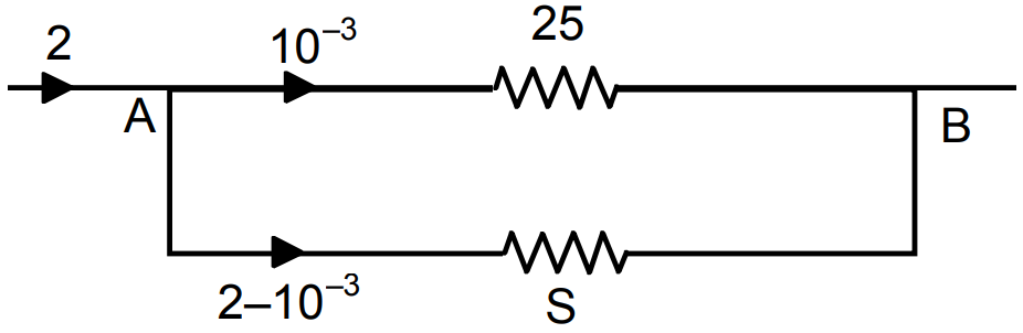 $\text{G}=25\Omega,\text{lg}=1\text{ma},\text{l}=2\text{A},\text{S}=?$
Potential across A B is same
$25\times10^{-3}=(2-10^{-3})\text{S}$
$\Rightarrow\text{S}=\frac{25\times10^{-3}}{2-10^{-3}}=\frac{25\times10^{-3}}{1.999}$
$=12.5\times10^{-3}=1.25\times10^{-2}.$ View full question & answer→Question 225 Marks
A heater coil is to be constructed with a nichrome wire $(\rho=1.0\times10^{-6}\Omega-\text{m})$which can operate at 500W when connected to a 250V supply.
- What would be the resistance of the coil?
- If the cross-sectional area of the wire $0.5mm^2,$ what length of the wire will be needed?
- If the radius of each turn is 4.0mm, how many turns will be there in the coil?
Answer$\text{f}=1\times10^{-6}\Omega\text{m}$
$\text{P}=500\text{W}$
$\text{E}=250\text{v}$
- $\text{R}=\frac{\text{V}^2}{\text{P}}$
$=\frac{250\times250}{500}=125\Omega$
- $\text{A}=0.5\text{mm}^2$
$=0.5\times10^{-6}\text{m}^2$
$=5\times10^{-7}\text{m}^2$
$\text{R}=\frac{\text{fI}}{\text{A}}=\text{l}=\frac{\text{RA}}{\text{f}}$
$=\frac{125\times5\times10^{-7}}{1\times10^{-6}}$
$=625\times10^{-1}=62.5\text{m}$
- $62.5=2\pi\text{r}\times\text{n}$
$62.5=3\times3.14\times4\times10^{-3}\times\text{n}$
$\Rightarrow\text{n}=\frac{62.5}{2\times3.14\times4\times10^3}$
$\Rightarrow\text{n}=\frac{62.5\times10^{-3}}{8\times3.14}\approx2500\ \text{turns}$ View full question & answer→Question 235 Marks
A bulb with rating 250V, 100W is connected to a power supply of 220V situated 10m away using a copper wire of area of cross-section $5mm^2.$ How much power will be consumed by the connecting wires? Resistivity of copper $1.7\times10^{-8}\Omega-\text{m}$.
Answer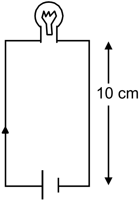
$\text{V}=250\text{V}$
$\text{P}=100\text{w}$
$\text{R}=\frac{\text{v}^2}{\text{P}}=\frac{(250)^2}{100}=625\Omega$
Resistance of wire $=\text{R}=\frac{\text{fl}}{\text{A}}=1.7\times10^{-8}\times\frac{10}{5\times10^{-6}}$
$=0.034\Omega$
$\therefore$ The effect in resistance $=625.034\Omega$
$\therefore$ The current in the conductor $=\frac{\text{V}}{\text{R}}=\Big(\frac{220}{625.034}\Big)\text{A}$
$\therefore$ The power supplied by one side of connecting wire $=\Big(\frac{220}{625.034}\Big)^2\times0.034$
$\therefore$ The total power supplied $=\Big(\frac{220}{625.034}\Big)^2\times0.034\times2$
$\Rightarrow0.0084\text{w}=8.4\text{mw}$ View full question & answer→Question 245 Marks
If the reading of the ammeter, $A_1$ in the figure. is 2.4A, what will be the readings of ammeters $A_2$ and $A_3?$ Neglect the resistances of the ammeters.
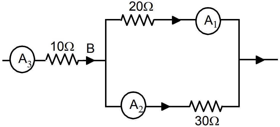
Answer$A_1 = 2.4A$
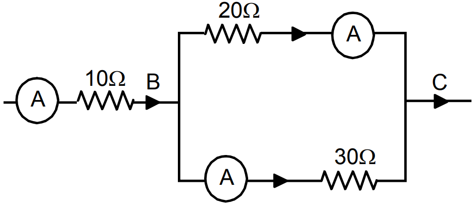
Since $A_1$ and $A_2$ are in parallel,
$\Rightarrow20\times2.4=30\times\text{X}$
$\Rightarrow\text{x}=\frac{20\times2.4}{30}=1.6\text{A}.$
Reading in Ammeter $A_2$ is 1.6A.
$\text{A}_3=\text{A}_1+\text{A}_2=2.4+1.6=4.0\text{A}.$ View full question & answer→Question 255 Marks
Three bulbs, each with a resistance of $180\Omega,$ are connected in parallel to an ideal battery of emf 60V. Find the current delivered by the battery when.
(a) all the bulbs are switched on, (b) two of the bulbs are switched on and (c) only one bulb is switched on.
Answer
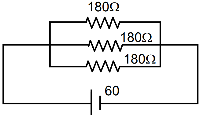
- $\text{R}_\text{eff}=\frac{180}{3}=60\Omega$
$\text{i}=\frac{60}{60}=1\text{A}$
- $\text{R}_\text{eff}=\frac{180}{2}=90\Omega$
$\text{i}=\frac{60}{90}=0.67\text{A}$
- $\text{R}_\text{eff}=180\Omega\Rightarrow\text{i}=\frac{60}{180}=0.33$
View full question & answer→Question 265 Marks
A servo voltage stabiliser restricts the voltage output to 220V ± 1%. If an electric bulb rated at 220V, 100W is connected to it, what will be the minimum and maximum power consumed by it?
AnswerOutput voltage $= 220 ± 1%$
$1% of 220V = 2.2v$
The resistance of bulb $\text{R}=\frac{\text{V}^2}{\text{P}}$
$=\frac{(220)^2}{100}=484\Omega$
- For minimum power consumed $V_1 = 220 - 1% = 220 – 2.2 = 217.8$
$\therefore\text{i}=\frac{\text{V}_1}{\text{R}}=\frac{217.8}{484}=0.45\text{A}$
Power consumed $=\text{i}\times\text{V}_1=0.45\times217.8=98.01\text{W}$
- for maximum power consumed $V_2= 220 + 1% = 220 + 2.2 = 222.2$
$\therefore\text{i}=\frac{\text{V}_2}{\text{R}}=\frac{222.2}{484}=0.459$
Power consumed $= i \times V_2 = 0.459 \times 222.2 = 102W$ View full question & answer→Question 275 Marks
A capacitor of capacitance $8.0\mu\text{F}$ is connected to a battery of emf 6.0V through a resistance of $24\Omega.$ Find the current in the circuit (a) just after the connections are made and (b) one time constant after the connections are made.
Answer$\text{C}=8\mu\text{F},\text{ E}=6\text{V},\text{R}=24\Omega$
- $\text{I}=\frac{\text{V}}{\text{R}}=\frac{6}{24}=0.25\text{A}$
- $\text{q}=\text{Q}\Big(1-\text{e}^{\frac{-\text{t}}{\text{RC}}}\Big)$
$=(8\times10^{-6}\times6)\big[1-\text{c}^{-1}\big]$
$=48\times10^{-6}\times0.63=3.024\times10^{-5}$
$\text{V}=\frac{\text{Q}}{\text{C}}=\frac{3.024\times10^{-5}}{8\times10^{-6}}=3.78$
$\text{E}=\text{V}+\text{iR}$
$\Rightarrow6=3.78+\text{i}24$
$\Rightarrow\text{i}=0.09\mathring{\text{A}}$ View full question & answer→Question 285 Marks
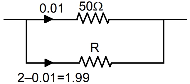
A voltmeter coil has resistance $50.0\Omega$ and a resistor of $1.15\text{k}\Omega$ is connected in series. It can read potential differences up to 12 volts. If this same coil is used to construct an ammeter that can measure currents up to 2.0A, what should be the resistance of the shunt used?
Answer
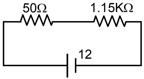
 $\text{R}_\text{eff}=(1150+50)\Omega=1200\Omega$
$\text{i}=\Big(\frac{12}{1200}\Big)\text{A}=0.01\text{A}.$
(The resistor of $50\Omega$ can tolerate)
Let R be the resistance of sheet used.
The potential across both the resistors is same.
$0.01\times50=1.99\times\text{R}$
$\Rightarrow\text{R}=\frac{0.01\times50}{1.99}=\frac{50}{199}=0.251\Omega$ View full question & answer→Question 295 Marks
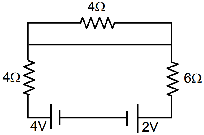
Find the currents through the three reaiators shown in figure.
Answer
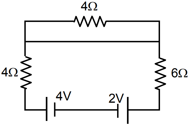
- Current through (1) $4\Omega$ resistor = 0
- Current through (2) and (3)
net E = 4V - 2V = 2V
(2) and (3) are in series,
$\text{R}_\text{eff}=4+6=10\Omega$
$\text{i}=\frac{2}{10}=0.2\text{A}$
Current through (2) and (3) are 0.2A. View full question & answer→Question 305 Marks
Consider a wire of length 4m and cross-sectional area $1mm^2$ carrying a current of 2A. If each cubic metre of the material contains $10^{29}$ free electrons, find the average time taken by an electron to cross the length of the wire.
Answer$\ell=4\text{m},\text{A}=1\text{mm}^2=1\times10^{-6}\text{m}^2$
$\text{I}=2\text{A},\text{n/V}=10^{29},\text{t}=?$
$\text{i}=\text{n AV}_\text{d}\text{ e}$
$\Rightarrow\text{e}=10^{29}\times1\times10^{-6}\times\text{V}_\text{d}\times1.6\times10^{-19}$
$\Rightarrow\text{V}_\text{d}=\frac{2}{10^{29}\times10^{-6}\times1.6\times10^{-19}}$
$=\frac{1}{0.8\times10^4}=\frac{1}{8000}$
$\text{t}=\frac{\ell}{\text{V}_\text{d}}=\frac{4}{\frac{1}{8000}}=4\times8000$
$=32000=3.2\times10^4\text{sec}.$
View full question & answer→Question 315 Marks
A parallel-plate capacitor of plate area $40cm^2$ and separation between the plates 0.10mm, is connected to a battery of emf 2.0V through a $16\Omega$ resistor. Find the electric field in the capacitor 10ns after the connections are made.
Answer$\text{A}=40\text{m}^2=40\times10^{-4}$
$\text{d}=0.1\text{mm}=1\times10^{-4}\text{m}$
$\text{R}=16\Omega;\text{ emf}=2\text{V}$
$\text{C}=\frac{\text{E}_0\text{A}}{\text{d}}=\frac{8.85\times10^{-12}\times40\times10^{-4}}{1\times10^{-4}}$ $=35.4\times10^{-11}\text{F}$
Now, $\text{E}=\frac{\text{Q}}{\text{AE}_0}\Big(1-\text{e}^{\frac{-\text{t}}{\text{RC}}}\Big)=\frac{\text{CV}}{\text{AE}_0}\Big(1-\text{e}^{\frac{-\text{t}}{\text{RC}}}\Big)$
$=\frac{35.4\times10^{-11}\times2}{40\times10^{-4}\times8.85\times10^{-12}}\Big(1-\text{e}^{-1.76}\Big)$
$=1.655\times10^{-4}=1.7\times10^{-4}\text{V/ m}.$
View full question & answer→Question 325 Marks
A battery of emf 100V and a resistor of resistance $10\text{k}\Omega$ are joined in series. This system is used as a source to supply current to an external resistance R. If R is not greater than $100\Omega,$ the current through it is constant up to two significant digits. Find its value. This is the basic principle of a constant-current source.
Answer$\text{E}=100\text{V},\text{R}'=100\text{k}\Omega=100000\Omega$
$\text{R}=1-100$
When no other resister is added or R = 0.
$\text{i}=\frac{\text{E}}{\text{R}'}=\frac{100}{100000}=0.001\text{Amp}$
When R = 1
$\text{i}=\frac{100}{100000+1}=\frac{100}{100001}=0.0009\text{A}$
When R = 100
$\text{i}=\frac{100}{100000+100}=\frac{100}{100100}=0.000999\text{A}.$
Upto R = 100 the current does not upto 2 significant digits. Thus it proved.
View full question & answer→Question 335 Marks
Figure. shows an arrangement to measure the emf $\in$ and internal resistance r of a battery. The voltmeter has a very high resistance and the ammeter also has some resistance. The voltmeter reads 1.52V when the switch S is open. When the switch is closed, the voltmeter reading drops to 1.45V and the ammeter reads 1.0A. Find the emf and the internal resistance of the battery.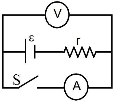
Answer
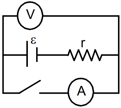
- When switch is open, no current passes through the ammeter. In the upper part of the circuit the Voltmenter has $\infty$ resistance. Thus current in it is 0.
$\therefore$ Voltmeter read the emf. (There is not Pot. Drop across the resistor).
- When switch is closed current passes through the circuit and if its value of i.
The voltmeter reads
$\in-\text{ir}=1.45$
$\Rightarrow1.52-\text{ir}=1.45$
$\Rightarrow\text{ir}=0.07$
$\Rightarrow1\text{r}=0.07\Rightarrow\text{r}=0.07\Omega.$ View full question & answer→Question 345 Marks
A $20\mu\text{F}$ capacitor is joined to a battery of emf 6.0V through a resistance of $100\Omega.$ Find the charge on the capacitor 2.0ms after the connections are made.
Answer$\text{C}=20\times10^{-6}\text{F, E}=6\text{V, R}=100\Omega$
$\text{t}=2\times10^{-3}\text{sec}$
$\text{q}=\text{EC}\Big(1-\text{e}^\frac{-\text{t}}{\text{RC}}\Big)$
$=6\times20\times10^{-6}\bigg(1-\text{e}^{\frac{-2\times10^{-3}}{100\times20\times10^{-6}}}\bigg)$
$=12\times10^{-5}(1-\text{e}^{-1})$ $=7.12\times0.63\times10^{-5}=7.56\times10^{-5}$
$=75.6\times10^{-6}=76\mu\text{c}.$
View full question & answer→Question 355 Marks
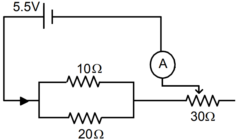
The resistance of the rheostat shown in the figure. is $30\Omega.$ Neglecting the meter resistance, find the minimum and maximum currents through the ammeter as the rheostat is varied.
Answer
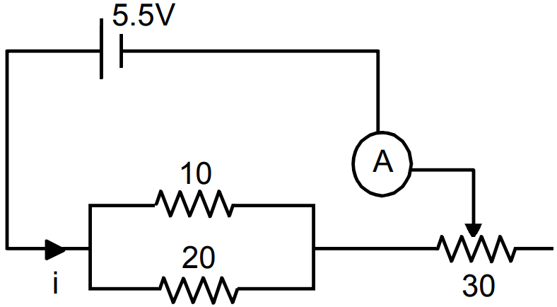
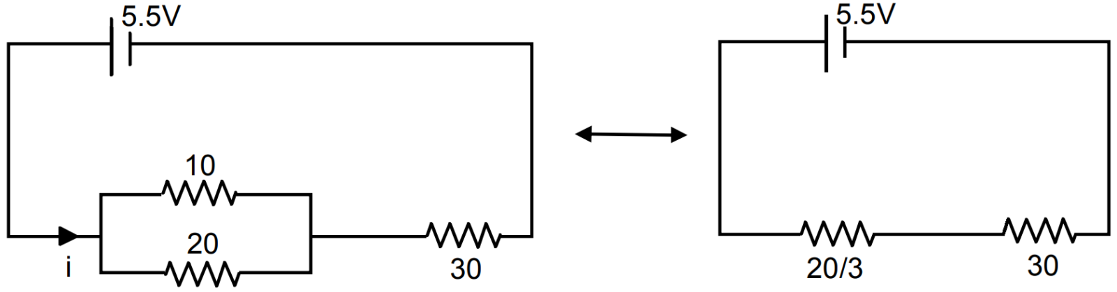 $\text{i}_\text{min}=\frac{5.5\times3}{110}=0.15$
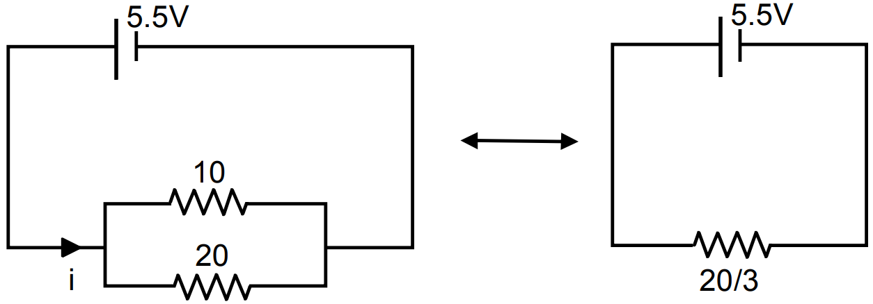
$\text{i}_\text{min}=\frac{5.5\times3}{20}=\frac{16.5}{20}=0.825.$ View full question & answer→Question 365 Marks
Find the charge required to flow through an electrolyte to liberate one atom of.
- A monovalent material.
- A divalent material.
Answer
- 1eq. mass of the substance requires 96500 coulombs
Since the element is monoatomic, thus eq. mass = mol. Mass
$6.023 \times 10^{23}$ atoms require 96500C
1 atoms require $\frac{96500}{6.023\times10^{23}}\text{C}=1.6\times10^{-19}\text{C}$
- Since the element is diatomic eq.mass = $=\frac{1}{2}\text{mol.mass}$
$\therefore\Big(\frac{1}2{}\Big)\times6.023\times10^{23}$ atoms 2eq. 96500C
$\Rightarrow1\ \text{atom require}=\frac{96500\times2}{6.023\times10^{23}}$
$=3.2\times10^{-19}\text{C}$ View full question & answer→Question 375 Marks
The current in a conductor and the potential difference across its ends are measured by an ammeter and a voltmeter. The meters draw negligible currents. The ammeter is accurate but the voltmeter has a zero error (that is, it does not read zero when no potential difference is applied). Calculate the zero error if the readings for two different conditions are 1.75A, 14.4V and 2.75A, 22.4V.
AnswerLet the voltmeter reading when, the voltage is 0 be X.
$\frac{\text{l}_1\text{R}}{\text{l}_2\text{R}}=\frac{\text{V}_1}{\text{V}_2}$
$\Rightarrow\frac{1.75}{2.75}=\frac{14.4-\text{V}}{22.4-\text{V}}$
$\Rightarrow\frac{0.35}{0.55}=\frac{14.4-\text{V}}{22.4-\text{V}}$
$\Rightarrow\frac{0.07}{0.11}=\frac{14.4-\text{V}}{22.4-\text{V}}$
$\Rightarrow\frac{7}{11}=\frac{14.4-\text{V}}{22.4-\text{V}}$
$\Rightarrow7(22.4-\text{V})=11(14.4-\text{V})$
$\Rightarrow156.8-7\text{V}=158.4-11\text{V}$
$\Rightarrow(7-11)\text{V}=156.8-158.4\Rightarrow-4\text{V}=-1.6$
$\Rightarrow\text{V}=0.4\text{V}.$
View full question & answer→Question 385 Marks
Electrons give up energy at the rate of $RI^2$ per second to the thermal energy. What time scale would one associate with energy in problem (a)? n = no of electron/volume $= 10^{29}/m^3,$ length of circuit = 10cm, cross-section $= A = (1mm)^2.$
AnswerOhmic loss (Power loss) is $P = I^2R = 6 \times 12 = 6W = 6J/s$
Since, the energy dissipated per unit time is the power dissipated
So, $\text{P}=\frac{\text{E}}{\text{t}}$
Therefore, $E = P × t$
or $\text{t}=\frac{\text{E}}{\text{P}}=\frac{2\times10^{-17}}{6}\approx10^{-17}\text{S}$
Important Point: The energy dissipated per unit time is the power dissipated $\text{P}=\frac{\Delta\text{W}}{\Delta\text{t}}$ and,
The power across a resistor is $P = I^2R.$
View full question & answer→Question 395 Marks
An electric kettle used to prepare tea, takes 2 minutes to boil 4 cups of water (1 cup contains 200cc of water) if the room temperature is 25C.
- If the cost of power consumption is Rs. 1.00 per unit (1 unit - 1000 watt-hour), calculate the cost of boiling 4 cups of water.
- What will be the corresponding cost if the room temperature drops to 5°C?
Answer
- Volume of water boiled $= 4 × 200cc = 800cc$
$T_1 = 25^\circ C$
$T_2 = 100^\circ C$
$\Rightarrow T_2 – T_1 = 75^\circ C$
Mass of water boiled = 800 × 1 = 800gm = 0.8kg(heat req.) $=\text{MS}\Delta\theta=0.8\times4200\times75=252000\text{J}.$
1000 watt-hour = 1000 × 3600 watt-sec = 1000 × 3600J
No. of units $=\frac{252000}{1000\times3600}=0.07=7\ \text{paise}$
- $\text{Q}=\text{mS}\Delta\text{T}=0.8\times4200\times95\text{J}$
No. of units $=\frac{0.8\times4200\times95}{1000\times3600}=0.0886\approx0.09$
Money consumed = 0.09 Rs = 9 paise. View full question & answer→Question 405 Marks
The potentiometer wire AB shown in figure. is 50cm long. When AD = 30cm, no deflection occurs in the galvanometer. Find R.
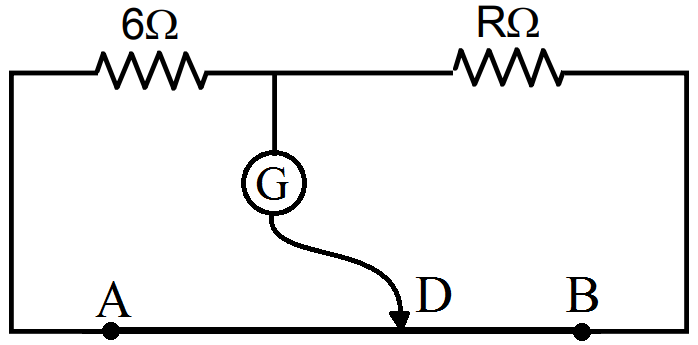
AnswerThe deflections does not occur in galvanometer if the condition is a balanced wheatstone bridge.
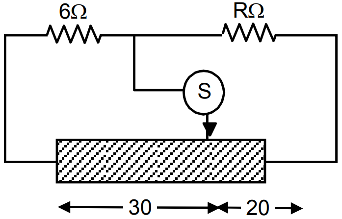
Let Resistance/ unit length = r.
Resistance of 30m length = 30r.
Resistance of 20m length = 20r.
For balanced wheatstones bridge $=\frac{6}{\text{R}}=\frac{30\text{r}}{20\text{r}}$
$\Rightarrow30\text{R}=20\times6\Rightarrow\text{R}=\frac{20\times6}{3}=4\Omega.$ View full question & answer→Question 415 Marks
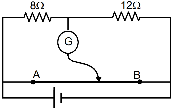
The potentiometer wire AB shown in the figure. is 40cm long. Where should the free end of the galvanometer be connected on AB so that the galvanometer may show zero deflection?
Answer
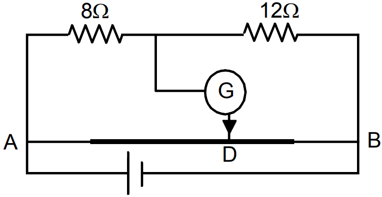 If the wire is connected to the potentiometer wire so that $\frac{\text{R}_\text{AD}}{\text{R}_\text{DB}}=\frac{8}{12},$ then according to wheat stone’s bridge no current will flow through galvanometer.
$\frac{\text{R}_\text{AB}}{\text{R}_\text{DB}}=\frac{\text{L}_\text{AB}}{\text{L}_\text{B}}=\frac{8}{12}=\frac{2}{3}$ (Acc. To principle of potentiometer).
$\text{I}_\text{AB}+\text{I}_\text{DB}=40\text{cm}$
$\Rightarrow\text{I}_\text{DB}\frac{2}{3}+\text{I}_\text{DB}=40\text{cm}$
$\Rightarrow\Big(\frac{2}{3}+1\Big)\text{I}_\text{DB}=40\text{cm}$
$\Rightarrow\frac{5}{3}\text{I}_\text{DB}=40$
$\Rightarrow\text{L}_\text{DB}=\frac{40\times3}{5}=24\text{cm}.$
$\text{I}_\text{AB}=(40-24)\text{cm}=16\text{cm}.$ View full question & answer→Question 425 Marks
In the given circuit, a metre bridge is shown in the balanced state. The metre bridge wire has a resistance of $1\Omega\text{cm}-1$. Calculate the unknown resistance X and the current drawn from the battery of a negligible internal resistance if the magnitude of Y is $6\Omega$ If at the balancing point, we interchange the position of galvanometer and the cell, how it will affect the position of the galvanometer?
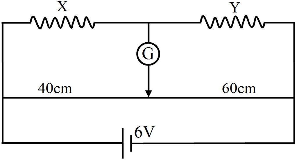
AnswerAt balanced state
$\frac{\text{X}}{\text{Y}}=\frac{40}{60}=\frac{2}{3}\Rightarrow\text{X}=\frac{2}{3}\text{Y}=\frac{2}{3}\times6$ $\therefore\text{X}=4\Omega$ $4\Omega$ and $6\Omega$ are in series, the equivalent resistance is given by, Req. $=4\Omega+6\Omega=10\Omega$ $4\Omega$ and $6\Omega$ are in series Req. $=10\Omega$ Resistance of bridge wire = 1 ohm/cm × 100cm $=100\Omega$ $10\Omega$ and $100\Omega$ are in parallel, $=\frac{1000}{110}\Omega=9.09\Omega,$ Current $=\frac{6}{9.09}$ There will be no change in the balancing length if we interchange position of galvanometer and cell. View full question & answer→Question 435 Marks
Find the current through the $10\Omega$ resistor shown in figure.
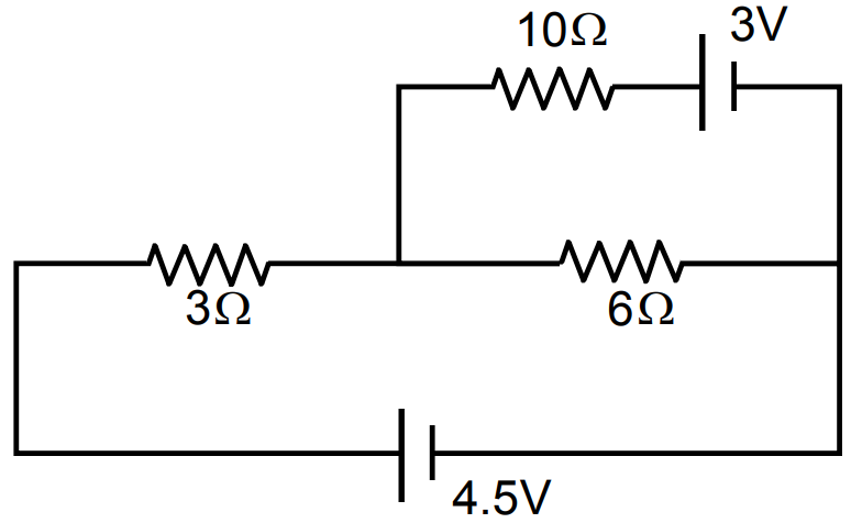
AnswerIn the circuit ADCBA,
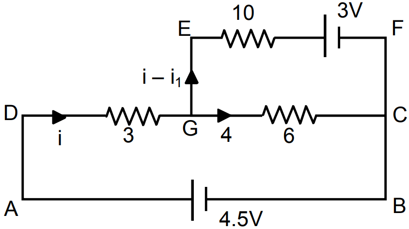
$3\text{i}+6\text{i}_1-4.5=0$
In the circuit GEFCG,
$3\text{i}+6\text{i}_1=4.5$
$=10\text{i}-10\text{i}_1-6\text{i}_1=-3$
$\Rightarrow[10\text{i}+16\text{i}_1=-3]3\ ...(1)$
$[3\text{i}+6\text{i}_1=4.5]10\ ...(2)$
From (1) and (2)
$-108\text{i}_1=-54$
$\Rightarrow\text{i}_1=\frac{54}{108}=\frac{1}{2}=0.5$
$3\text{i}+6\times\frac{1}{2}-4.5=0$
$3\text{i}-1.5=0\Rightarrow\text{i}=0.5$
Current through $10\Omega$ resistor = 0A. View full question & answer→Question 445 Marks
Establish a relation between electric current and drift velocity.
OR
Prove that the current density of a metallic conductor is directly proportional to the drift speed of electrons.
AnswerRelation between electric current and drift velocity: Consider a uniform metallic wire XY of length l and cross-sectional area A. A potential difference V is applied across the ends X and Y of the wire. This causes an electric field at each point of the wire of strength.
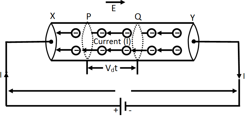
$\text{E}=\frac{\text{V}}{\text{l}}\dots\text{(i)}$ Due to this electric field, the electrons gain a drift velocity vd opposite to direction of electric field. If q be the charge passing through the cross-section of wire in t seconds, then $\text{Current in write I}=\frac{\text{q}}{\text{r}}\dots\text{(ii)}$ The distance traversed by each electron in time t = average velocity × time = vd t If we consider two planes P and Q at a distance vd t in a conductor, then the total charge flowing in time t will be equal to the total charge on the electrons present within the cylinder PQ. The volume of this cylinder = cross sectional area × height = A vd t If n is the number of free electrons in the wire per unit volume, then the number of free electrons in the cylinder = n(Avd t) If charge on each electron is $-e (e = 1.6 \times 10^{-19}C)$, then the total charge flowing through a cross-section of the wire $q = (nA_vd t) (-e) = –neA_vd t ...(iii)$ $\therefore$ Current flowing in the wire, $\text{I}=\frac{\text{q}}{\text{t}}=\frac{-\text{v}}{\text{t}}$ i.e., current I = -neAvd ...(iv) This is the relation between electric current and drift velocity. Negative sign shows that the direction of current is opposite to the drift velocity. Numerically I = -neAvd ...(v) $\therefore$ Current density, $\text{J}=\frac{\text{I}}{\text{A}}=\text{d}$ $\Rightarrow\text{J}\propto\text{vd.}$ That is, current density of a metallic conductor is directly proportional to the drift velocity. View full question & answer→Question 455 Marks
(a) Find the current in the $20\Omega$ resistor shown in the figure. (b) If a capacitor of capacitance $4\mu\text{F}$ is joined between the points A and B, what would be the electrostatic energy stored in it in steady state?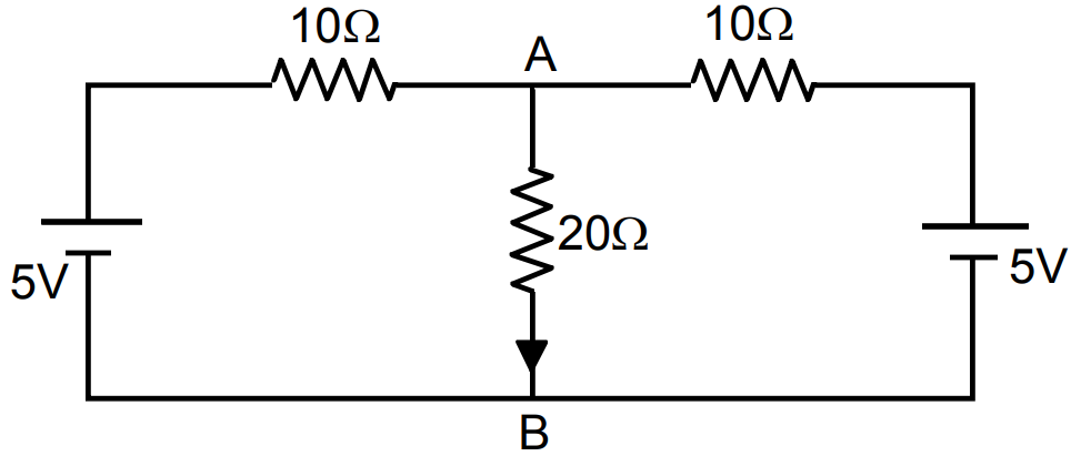
AnswerTaking circuit, ABCDA,
$10\text{i}+20(\text{i}-\text{i}_1)-5=0$
$\Rightarrow10\text{i}+20\text{i}-20\text{i}_1-5=0$
$\Rightarrow30\text{i}-20\text{i}_1-5=0\ ...(1)$
Taking circuit ABFEA,
$20\text{i}(\text{i}-\text{i}_1)-5-10\text{i}_1=0$
$\Rightarrow10\text{i}-20\text{i}_1-10\text{i}_1-5=0$
$\Rightarrow20\text{i}-30\text{i}_1-5=0\ ...(2)$
From (1) and (2)
$(90-40)\text{i}_1=0$
$\Rightarrow\text{i}_1=0$
$30\text{i}-5=0$
$\Rightarrow\text{i}=\frac{5}{30}=0.16\text{A}$
Current through $20\Omega$ is 0.16A. View full question & answer→Question 465 Marks
Write the mathematical relation for the resistivity of a material in terms of relaxation time, number density, mass and charge of charge carriers in it. Explain using this relation, why the resistivity of a metal increases and that of a semiconductor decreases with rise in temperature.
AnswerResistivity of a material, $\rho=\frac{\text{m}}{\text{ne}^2\tau}$
Where m is mass, e is charge on charge carrier, n is number density and τ is relaxation time.
For a metallic conductor: When temperature of a metal increases, the number of collisions of electrons with ion-lattice increases, so relaxation time decreases, as resistivity $\rho\propto\frac{1}{\tau}$ so resistivity of material increases with rise of temperature.
For a semiconductor: When temperature increases, the covalent bonds between valence electrons of atoms of semiconductor break, so more charge carriers (electrons and holes) becomes free. In other words the number density of charge carriers increases $\rho\propto\frac{1}{\text{n}},$ so resistivity of semiconductor decreases with the rise of temperature.
View full question & answer→Question 475 Marks
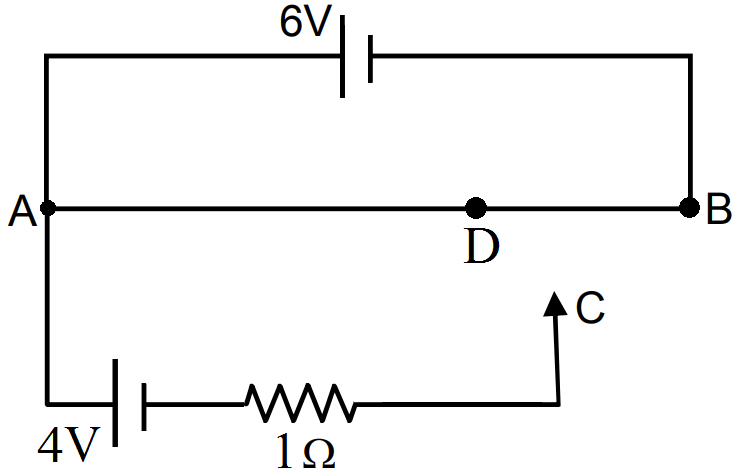
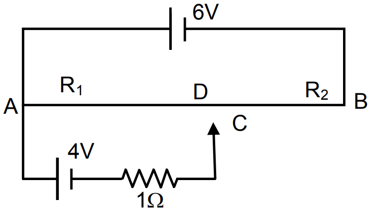
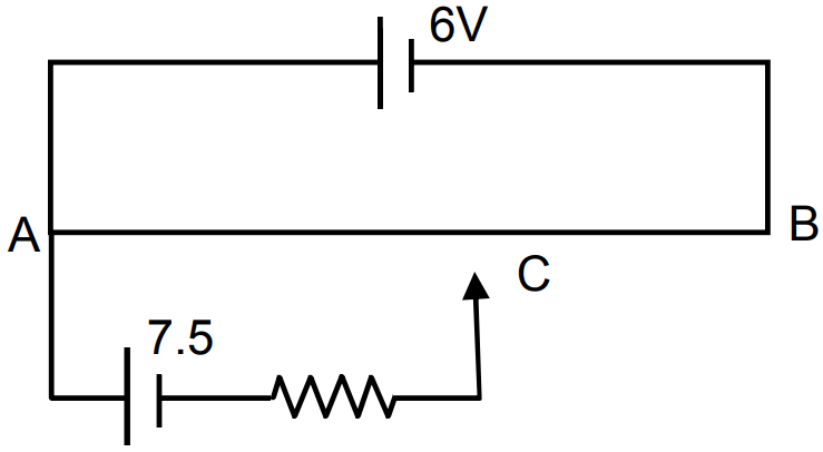
A 6 volt battery of negligible internal resistance is connected across a uniform wire AB of length 100cm. The positive terminal of another battery of emf 4V and internal resistance $1\Omega$ is joined to the point A, as shown in the figure. Take the potential at B to be zero. (a) What are the potentials at the points A and C? (b) At which point D of the wire AB, the potential is equal to the potential at C? (c) If the points C and D are connected by a wire, what will be the current through it? (d) If the 4V battery is replaced by a 7.5V battery, what would be the answers of parts (a) and (b)?
Answer
- Potential difference between A and B is 6V.
B is at 0 potential.
Thus potential of A point is 6V.
The potential difference between Ac is 4V.
$\text{V}_\text{A}-\text{V}_\text{C}=0.4$
$\text{V}_\text{C}=\text{V}_\text{A}-4=6-4=2\text{V}$
- The potential at $\text{D}=2\text{V},\text{V}_\text{AD}=4\text{V};\text{V}_\text{BD}=\text{OV}$
Current through the resisters $R_1$ and $R_2$ are equal
Thus, $\frac{4}{\text{R}_1}=\frac{2}{\text{R}_2}$
$\Rightarrow\frac{\text{R}_1}{\text{R}_2}=2$
$\Rightarrow\frac{\text{I}_1}{\text{I}_2}=2$ (Acc. to the law of potentiometer)
$\text{I}_1+\text{I}_2=100\text{cm}$
$\Rightarrow\text{I}_1+\frac{\text{I}_1}{2}=100\text{cm}\Rightarrow\frac{3\text{I}_1}{2}=100\text{cm}$
$\Rightarrow\text{I}_1=\frac{200}{3}\text{cm}=66.67\text{cm}.$
$\text{AD}=66.67\text{cm}$
- When the points C and D are connected by a wire current flowing through it is 0 since the points are equipotential.
- Potential at A = 6 v
Potential at C = 6 - 7.5 = -1.5V
The potential at B = 0 and towards A potential increases.
Thus -ve potential point does not come within the wire. View full question & answer→Question 485 Marks
Suppose there is a circuit consisting of only resistances and batteries. Suppose one is to double (or increase it to n-times) all voltages and all resistances. Show that currents are unaltered.
AnswerLet us first assume the equivalent internal resistance of the battery is $R_{eff}$, the equivalnet external resistance R and the equivalent voltage of the battery is $V_{eff}.$
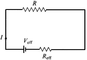
Now by applying Ohm's law,
Then current through R is given by
$\text{I}=\frac{\text{V}_\text{eff}}{\text{R}_\text{eff}+\text{R}}$
Now according to the question if all the resistances and the effective voltage are increased n-times, then we have
$\text{V}_\text{eff}^\text{new}=\text{nV}_\text{eff},\text{R}_\text{eff}^\text{new}=\text{nR}_\text{eff}$
and $\text{R}^\text{new}=\text{nR}$
Then, the new current is given by
$\text{I}'=\frac{\text{nV}_\text{eff}}{\text{nR}_\text{eff}+\text{nR}}=\frac{\text{n}(\text{V}_\text{eff})}{\text{n}(\text{R}_\text{eff}+\text{R})}=\frac{(\text{V}_\text{eff})}{(\text{R}_\text{eff}+\text{R})}=\text{I}$
The last result of two equations is same, so we can say that current remains the same. View full question & answer→Question 495 Marks
Find the circuit in the three resistors shown in the figure.
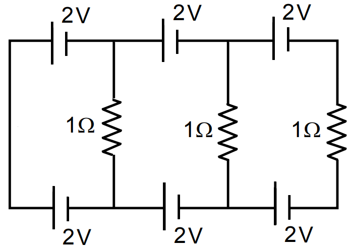
AnswerIn AHGBA,
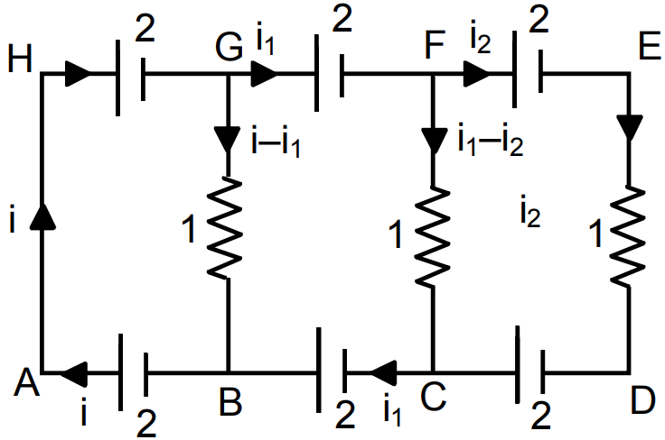
$2+(\text{i}-\text{i}_1)-2=0$
$\Rightarrow\text{i}-\text{i}_1=0$
In circuit CFEDC,
$-(\text{i}_1-\text{i}_2)+2+\text{i}_2-2=0$
$\Rightarrow\text{i}_2-\text{i}_1+\text{i}_2=0\Rightarrow2\text{i}_2-\text{i}_1=0$
In circuit BGFCB,
$-(\text{i}_1-\text{i}_2)+2+(\text{i}_1-\text{i}_2)-2=0$
$\Rightarrow\text{i}_1-\text{i}+\text{i}_1-\text{i}_2=0$
$\Rightarrow2\text{i}_1-\text{i}-\text{i}_2=0\ ...(1)$
$\Rightarrow\text{i}_1-(\text{i}-\text{i}_1)-\text{i}_2=0$
$\Rightarrow\text{i}_1-\text{i}_2=0\ ...(2)$
$\therefore\text{i}_1-\text{i}_2=0$
From (1) and (2)
Current in the three resistors is 0. View full question & answer→Question 505 Marks
Consider $N = n_1n_2$ identical cells, each of emf $\in$ and internal resistance r. Suppose $n_1$ cells are joined in series to form a line and $n_2$ such lines are connected in parallel. The combination drives a current in an external resistance R. (a) Find the current in the external resistance. (b) Assuming that $n_1$ and $n_2$ can be continuously varied, find the relation between $n_1, n_2, R$ and r for which the current in R is maximum.
Answer
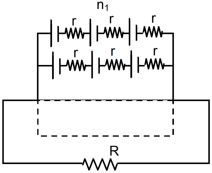
- Total emf $= n_1E$
in 1 row
Total emf in all news $= n_1E$
Total resistance in one row $= n_1r$
Total resistance in all rows $=\frac{\text{n}_1\text{r}}{\text{n}_2}$
Net resistance $=\frac{\text{n}_1\text{r}}{\text{n}_2}+\text{R}$
Current $=\frac{\text{n}_1\text{E}}{\frac{\text{n}_1}{\text{n}_2\text{r}}+\text{R}}=\frac{\text{n}_1\text{n}_2\text{E}}{\text{n}_1\text{r}+\text{n}_2\text{R}}$
- $\text{I}=\frac{\text{n}_1\text{n}_2\text{E}}{\text{n}_1\text{r}+\text{n}_2\text{R}}$
for I = max,
$n_1r + n_2R =$ min
$\Rightarrow\Big(\sqrt{\text{n}_1\text{r}}-\sqrt{\text{n}_2\text{R}}\Big)^2+2\sqrt{\text{n}_1\text{rn}_2\text{R}}=\text{min}$
it is min, when
$\sqrt{\text{n}_1\text{r}}=\sqrt{\text{n}_2\text{R}}$
$\Rightarrow\text{n}_1\text{r}=\text{n}_2\text{R}$
I is max when $n_1r = n_2R.$ View full question & answer→