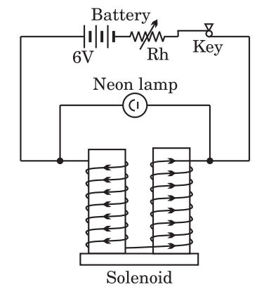
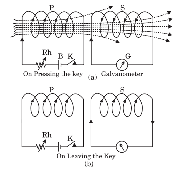
Question 15 MarksDifferentiate between self induction and mutual induction with examples.AnswerSelf Induction : "The phenomenon of electromagnetic induction in which on changing the main current in a coil, an induced current is developed in the same coil, is called self induction."Example : A solenoid having a large number of turns of insulated wire wound over soft iron core is connected in series with a 6 V battery, a rheostat and a tapping key.A neon lamp is connected in parallel with the solenoid. First press the tapping key and adjust the current in the circuit with the help of rheostat such that the lamp glows faintly. Now, as the tapping is stopped, the lamp glows brightly for a moment and then goes out. This is due to the fact that as the circuit is broken suddenly the magnetic flux linked with the coil of solenoid suddenly vanishes i.e. the rate of change of magnetic flux linked with the solenoid i.e. self induced emf is very large. Hence a large self induced current flows in the circuit which makes the bulb glow brightly for a moment.Mutual Induction : "It is the phenomenon of electromagnetic induction in which induced emf is produced in the another coil placed near by a coil in which the magnetic flux is changed by changing the current in this coil."The coil in which the magnetic flux is changed by passing an electric current through it or by changing the current already passing through it or by stopping the current already flowing through it is called the primary coil while the other coil in which the induced emf is produced is called secondary coil.Example : P is primary coil T and S is the secondary coil placed close to each other. The coil P is connected to a battery B, tapping key K and a rheostat Rh. The coil S is connected to a galvanometer G. As the key K in primary coil P circuit is closed a momentary deflection is seen in the galvanometer connected in secondary coil circuit. This is due to the fact that when the key K is pressed, current passes in the coil P and a magnetic field is produced around it. Some of the magnetic flux lines pass through S also. Thus on pressing the key K the number of flux lines passing through S increases from 0 to a definite value. Due to this change in the number of magnetic flux lines i.e. the magnetic flux an emf is induced in the coil S and its corresponding induced current flowing through S produces momentary deflection in galvanometer G. According to Lenz's law the induced current in S opposes the change in magnetic flux in P. hence the direction of induced current in S will be opposite to the direction of main current in the primary coil P [Fig. (a)]. When the key K in primary coil is released then again a momentary deflection is seen in the galvanometer G in secondary coil but now in the direction opposite to the previous direction. This is due to the fact that on releasing the key the current flowing through P reduces from its steady value to zero and hence the flux lines passing through S become zero. Hence again an induced emf is generated in S and corresponding induced current flows through it giving deflection in G. But according to Lenz's law this current opposes the decrease in magnetic flux in P, hence it tends to maintain the flux lines in S. Therefore now the direction of induced current in S flows in the same direction of current as was in P [Fig. (b)].Similarly, when the current flowing through P is varied (increased or decreased) with the help of rheostat Rh, there is a change in magnetic flux lines around it and also linked with S. Hence so long as the current in P is changing an induced current in S flows.All of this is due to mutual induction between P and S.View full question & answer→
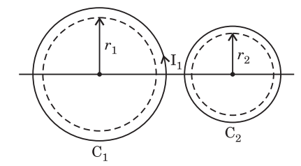
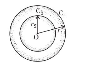
Question 25 Marks(a) Derive the expression for the magnetic energy stored in a evil.(b) Derive the expression for the mutual inductance between two plane coils.Answer(a) Magnetic Energy Stored in a coil: When a current is established in an inductor (coil) by connected, a source of emf across its ends then an emf is induced in it due to self induction. This emf opposses the rise of current through the coil. Hence work has to be done by the current to get its steady value against the induced emf.The energy for this work is obtained from the source of emf connected across the coil and this energy is stored as magnetic energy in the coil.Let dW be the work done in establishing a current I in the coil in time dt.Then, work $dW = eIdt$, where e is the induced emf$dW = [L(\frac{dI}{dt})]Idt = LIdI$ ($\because$ $e = L\frac{dI}{dt}$)Total work done in maintaining a steady current $I_{0}$ in the coil is given by$W = \int dW = \int_{0}^{I_{0}} LIdI = L[\frac{I^{2}}{2}]_{0}^{I_{0}} = \frac{1}{2}LI_{0}^{2}$ Magnetic Energy stored in the coil :$U=W \Rightarrow U=\frac{1}{2}LI_{0}^{2}$(b) Mutual Inductance between two plane coils:In adjoining figure two plane coils C1 and C2 are kept coaxially near each other. Let N1 be the number of turns in primary and N2 in secondary coil. If I1 current is flowing in primary coil, the magnetic field at the centre of the coil is given by :$B _1=\frac{\mu_0 N_1 I _1}{2 r_1}$where $r_1$ is the radius of the primary coil. The magnetic field lines are treating uniformerly into the secondary coil. Hence magnetic flux passing through each turn of secondary coil will be $\Phi_2= B _1 \times A _2$where $A_2$ = Area of cross-section of secondary coil =$\pi r_2^2$ in which $r_2$ is the radius of the secondary coil$\therefore \quad \Phi_2=\left(\frac{\mu_0 N_1 I _1}{2 r_1}\right) \times \pi r_2^2$or $\Phi_2=\left(\frac{\mu_0 \pi r_2^2}{2 r_1}\right) N _1 I _1$But coefficient inductance between these two coils is given by$M =\frac{ N _2 \Phi_2}{ I _1}$$\therefore \quad M =\frac{ N _2\left(\frac{\mu_0 \pi r_2^2}{2 r_1}\right) \cdot N _1 I _1}{ I _1}$$\Rightarrow \quad M =\left(\frac{\mu_0 \pi r_2^2}{ 2 r_1}\right) N _1 N _2$ ...(1)If the two coils are placed concentrically as shown in adjoining figure and $I_1$ be the current passed through coil C1 then magnetic field at the centre of this coil will be given by :$B _1=\frac{\mu_0 N_1 I _1}{2 r_1}$where, N1= Number of turns in this coil C1 r₁ = Radius of this coil C1 Since coil C2 is small, the magnetic field B1 may be considered uniform throughout the area of cross-section of C2.∴ Magnetic flux linked with the coil $C _2$ is given by :$\Phi_2= B _1 A_2=\frac{\mu_0 N_1 I _1}{2 r_1} \times \pi r_2^2$$\Rightarrow \quad \Phi_2=\left(\frac{\mu_0 \pi r_2^2}{2 r_1}\right) N _1 I _1$where, r2 = Radius of inner coil C2.But coefficient of mutual induction between these two coils is given by :$M =\frac{ N _2 \Phi_2}{ I _1}=\frac{ N _2\left(\frac{\mu_0 \pi r_2^2}{2 r_1}\right) N _1 I _1}{ I _1}$$\Rightarrow \quad M =\left(\frac{\mu_0 \pi r_2^2}{ 2 r _1}\right) N _1 N _2$ ...(2)where, N2 = Number of turns in the inner coil. Thus formula for M is the same as formula (1).In this way formula for M in both the situation is the same.View full question & answer→