Questions

4 Marks Questions

🎯

Test yourself on this topic

4 questions · timed · auto-graded

Question 14 Marks
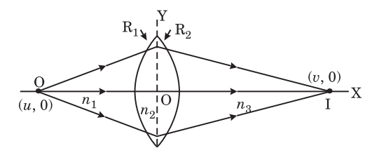
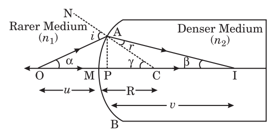
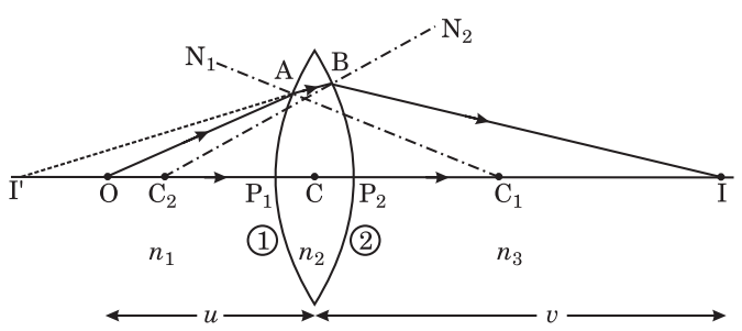
Establish the formula : $\frac{n_{2}}{v}-\frac{n_{1}}{u}=\frac{n_{2}-n_{1}}{R}$ for refraction at single curved surface, where symbols have their usual meanings.
Answer
In figure AB is a convex single refracting surface separating two media of refrective index n1 and n2 respectively where n1 > n2. O is the object placed in rarer medium $\left(n_1\right)$ and I is the image formed by the refraction at this surface formed in denser medium $\left(n_2\right)$.
Let i be the angle of incidence of ray OA and $r$ the angle of refraction in the denser medium i.e., ∠OAN = i and $\angle CAI =r$. Let $\angle AOP =\alpha, \angle AIP =\beta$ and $\angle ACP =\gamma$.
In triangle OAC$\quad$$i=\gamma+\alpha$
In triangle AIC,$\quad$$\gamma=\beta+r \Rightarrow r=\gamma-\beta$
If point A is very close to P, the angles $i, r, \alpha, \beta$ and $\gamma$ will be very small, therefore :
$\sin i = i$ and $\sin r = r$
From Snell's Law
Image
$\frac{\sin i}{\sin r}=\frac{n_2}{n_1}$
$\Rightarrow \quad \frac{i}{r}=\frac{n_2}{n_1}$
$\Rightarrow \quad \frac{\gamma+\alpha}{\gamma-\beta}=\frac{n_2}{n_1}$
$\Rightarrow \quad n_1(\gamma+\alpha)=n_2(\gamma-\beta)$
$\Rightarrow \quad n_1 \gamma+n_1 \alpha=n_2 \gamma-n_2 \beta$
$\Rightarrow \quad n_1 \alpha+n_2 \beta=\left(n_2-n_1\right) \gamma$ ...(1)
Let $h$ be the height of perpendicular drawn from A on principal axis i.e. $AM =h$. As $\alpha, \beta$ and $\gamma$ are very small angles.
Hence $\tan \alpha=\alpha, \tan \beta=\beta$ and $\tan \gamma=\gamma$
As point A is very close to point P so point M is coincident with P.
∴ From figure $\alpha=\tan \alpha=\frac{ AM }{ OM }=\frac{h}{ OP }=\frac{h}{-u}$
$\beta=\tan \beta=\frac{ AM }{ MI }=\frac{h}{ PI }=\frac{h}{+v}$
$\gamma=\tan \gamma=\frac{ AM }{ MC }=\frac{h}{ PC }=\frac{h}{+ R }$
On substituting these values in equation (1), we get
$n_1 \times\left(\frac{h}{-u}\right)+n_2\left(\frac{h}{v}\right)=\left(n_2-n_1\right) \frac{h}{R}$
$\Rightarrow \quad \frac{n_2}{v}-\frac{n_1}{u}=\frac{n_2-n_1}{R}$ (Hence proved)
To derive lens maker's formula $\frac{1}{f}=(n-1)\left(\frac{1}{R_1}-\frac{1}{R_2}\right)$.

View full question & answer
Question 24 Marks
What is the difference between Magnification and Magnifying power ?
Answer
MagnificationMagnifying power
(i) It is a liner magnificant which is equal to $\frac{h_2}{h_1}$.It is an angular magnification which is equals to $\frac{\angle \beta}{\angle \alpha}$.
(ii) Its value increases with the increase in V.Its value decreases with the increase in V.
(iii) Its value may be between $-\infty$ to $+\infty$.Its value may be between $\frac{ D }{f}$ and $l+\frac{ D }{f}$.
(iv) Under certain condition it is equal to magnifying power.It is a special condition of magnification when ve = D.
View full question & answer
Question 34 Marks
(a) What do you mean by equivalent lens? In a system of two lenses these are placed at a some distance from each other. Establish the formula for the equivalent focal length of the system.
(b) A lens converted by two curved surfaces of radius of curvature R1 and R2 is placed according to the following figure :
Image
Prove that: $\frac{n_3}{v}-\frac{n_1}{u}=\frac{n_2-n_1}{R_1}+\frac{n_3-n_2}{R_2}$
Answer
(a) Equivalent Lens : The lens which makes the image of an object placed infront of it at the same distance as made by the combination of two lenses in contact is called equivalent lens.
Equivalent Focal Length when two thin lenses placed at some distance apart : In fig. given below two thin lenses L1 and L2 of focal length. $f_1$ and $f_2$ are placed coaxially at distance 'd' apart.
Image
A ray of light, OA parallel to the common principal axis is incident on lens L1 at A and is refracted along AF1, where F1 is the second principal focus of L1. The deviation $\delta_1$ caused by thin lens L1 is given by :
$\delta_1 \approx \tan \delta_1=\frac{h_1}{f_1} \quad\left(\right.$ where $\left.C _1 A=h_1\right)$ ...(1)
The emergent ray from L1 traversing along AF is incident on the second lens L2 at B and is further refracted by lens along BF2, where F2 is the second principal focus of this lens. The deviation $\delta_2$ caused by this lens L2 is given by :.
$\delta_2 \approx \tan \delta_2=\frac{h_2}{f_2}\left(\right.$ where $\left.C _2 B=h_2\right)$ ...(2)
The emergent ray BF2 emerging from lens L2 when produced backward, meets the incident ray produced forward at D. Thus angle $\delta$ is the resultant deviation caused by the lens combination. Now it is obvious that a single lens placed in the position CD will cause the same deviation $\delta$ as that caused by the combination. Thus distance CF2 will be the second principal focal length of the combination say F. Hence,
$\delta \approx \tan \delta=\frac{ CD }{ F } \Rightarrow \delta=\frac{h_1}{F}$ ...(3)
But it is obvious from the figure that : $\delta=\delta_1+\delta_2$
Now, substituting the values of $\delta_1, \delta_2$ and $\delta $ in equations (1), (2) and (3) respectively, we get
$\frac{h_1}{F}=\frac{h_1}{f_1}+\frac{h_2}{f_2}$ ...(4)
Now in similar triangles $AC _1 F_1$ and $BC _2 F_1$, we have
$\frac{ AC _1}{ C _1 F_1}=\frac{ BC _2}{ C _2 F_1}$
$\Rightarrow \quad \frac{h_1}{f_1}=\frac{h_2}{ C _1 F_1- C _1 C _2}$
$\Rightarrow \quad \frac{h_1}{f_1}=\frac{h_2}{f_1-d}$
$\Rightarrow \quad h_2=\left(\frac{f_1-d}{f_1}\right) h_1$
On substituting this value of $h_2$ in equation (4), we get
$\frac{h_1}{F}=\frac{h_1}{f_1}+\left(\frac{f_1-d}{f_1 f_2}\right) \cdot h_1$
$\Rightarrow \quad \frac{1}{F}=\frac{1}{f_1}+\frac{f_1-d}{f_1 f_2}$
$\Rightarrow \quad \frac{1}{F}=\frac{1}{f_1}+\frac{f_1}{f_1 f_2}-\frac{d}{f_1 f_2}$
$\Rightarrow \quad \frac{1}{F}=\frac{1}{f_1}+\frac{f_1-d}{f_1 f_2}$ ...(5)
This is the formula for equivalent focal length of the combination.
Lens maker's formula when medium on both sides of the lens is not the same : Suppose that a convex lens 'L' made of glass of absolute refractive index n2 is placed at a place where the medium on the left side of the lens is of absolute refractive index n1 and that on right side of the lens is of absolute refractive index n3 (See Fig.). Here $n_2>n_1$ and $n_3>n_2$. In this figure P1 , P2 are the poles and C1 , C2 are the centres of curvature of the lens. Hence P1C1 = R1 and P2C2 = R2 are the radii of curvature of the first surface and second surface of the lens respectively marked as (1) and (2). C is optical centre of the lens. O is a point object placed on the principal axis of the lens. Here I' is the image of this object formed due to refraction at surface (1).
Image
Hence, here u = P1O and v = P1I', therefore on the basis of formula for refraction at single refracting surface for refraction at this surface, we have
$\frac{n_2}{ P _1 I ^{\prime}}-\frac{n_1}{ P _1 O }=\frac{n_2-n_1}{ R _1}$ ...(1)
This image I' serves as virtual object for the surface (2) of the lens. This surface forms the image of I' at I, where u = P2I' and v = P2I, therefore for the refraction at this surface, we have
$\frac{n_3}{ P _2 I }-\frac{n_2}{ P _2 I ^{\prime}}=\frac{n_3-n_2}{ R _2}$ ...(2)
But for thin lens the poles P1 and P2 of the two surfaces of the lens may be supposed to be coinciding with the optical centre C of the lens. Hence under this condition the above equations (1) and (2) can be written as follows :
$\frac{n_2}{ CI ^{\prime}}-\frac{n_1}{ CO }=\frac{n_2-n_1}{ R _1}$ ...(3)
and $\frac{n_3}{ CI }-\frac{n_2}{ CI ^{\prime}}=\frac{n_3-n_2}{ R _2}$ ...(4)
On adding equations (3) and (4), we have
$\frac{n_3}{ CI }-\frac{n_1}{ CO }=\frac{n_2-n_1}{ R _1}+\frac{n_3-n_2}{ R _2}$ ...(5)
But it is obvious that I is the final image of object 'O' formed by the lens due to combined effect of refraction at both surfaces of the lens. Thus we have $CO = u$ and CI = $v$.
Hence equation (5) can be written as follows :
$\frac{n_3}{v}-\frac{n_1}{u}=\frac{n_2-n_1}{ R _1}+\frac{n_3-n_2}{ R _2}$ ...(6)
(Hence proved)
This equation (6) represents lens maker's formula for the refraction of light by a thin lens when media on both sides of the lens are different.

View full question & answer
Question 44 Marks
Draw a neat labelled diagram of human eye. Explain shortsightedness and longsightedness eye defects giving their cause and method of removal showing ray diagram.
Answer
Labelled diagram of human eye : It is shown in adjacent figure (a).
Image
Eye Defects :
(1) Short sightedness or Myopiya : This defect is also known as nearsightedness. A short-sighted person cannot see objects placed beyond a certain distance from the eye. This distance is the short-sighted eye's far point. Nearsightedness can occur because (a) the eyeball is elongated, i.e., the distance between the lens and then retina is greater than normal, or (b) the maximum focal length of the lens (when the eye is relaxed) is less than usual.
Image
The result is that a parallel beam of light froma distant object converges short of the retina [Figure (a)]. However, a divergent beam from any point closer than the far point converges on the retina [Figure (b)]. This defect can be corrected by using a concave lens of appropriate focal length. The lens should be such that parallel rays from a distant object appear to come from the far point of the eye after refraction from it [(c)]. Suppose the focal length of the lens to be used is $f$. Then $u$ $=-\infty$ and $v=-d$ (the distance of the far point O from the concave lens), and from the lens formula,
$\frac{1}{-d}-\frac{1}{\infty}=\frac{1}{f} \Rightarrow f=-d$ ...(i)
The negative sign of the focal length shows that the lens is concave. The focal length of the lens should be equal to the distance of the far point of the eye.
(2) Long-sightedness or hypermetropia : The defect is also known as farsightedness or hypermetropia. The eye, in this case, cannot see objects within a certain distance from the eye. The minimum distance beyond which it can see clearly without straining is its near point. The possible causes of this defect are (a) the shortening of the eyeball, i.e., the distance between the lens and the retina is less than normal, or (2) the focal length of the lens is greater than usual.
Consequently, rays from any point, N', which is closer than the near point, N, converge behind the retina [Figure (a)], while rays from all points, N', beyond the near point converge on the retina [Figure (b)]. This defect can be corrected by using a convex lens of the appropriate focal length to make the divergent rays from an object placed at the normal near point, N, converge on the retina after refraction by the convex lens. Then rays from the object appear to come from the point N', the near point of the defective eye, and can be seen clearly [Figure (c)].
Image
Suppose the focal length of the convex lens used is $f$. Then $u =- D$ and $v=-d$ (the distance of the near point N' from the convex lens.) Thus, from the lens formula,
$\frac{1}{f}=\frac{1}{-d}-\frac{1}{- D }=\frac{d- D }{ D d} \Rightarrow f=\frac{ D d}{d- D }$ ...(ii)
In equation (ii), as d > D the focal length is positive, which shows that the lens used is convex. Since the image of an object placed at the normal near point is formed at the near point N' of the defective eye, the image of any object situated between N and N' wil be formed beyond the near point of the defective eye and seen clearly due to the eye's accomodating power.

View full question & answer