Whenever energy is given to a circuit containing a pure inductor of inductance L and a capacitor of capacitance C, the energy oscillates back and forth between the magnetic field of the inductor and the electric field of the capacitor. Thus the electrical oscillations of definite frequency are generated. These oscillations are called LC oscillations.
Generation of LC oscillations:
Let us assume that the capacitor is fully charged with maximum charge $Q _{ m }$ at the initial stage. So that the energy stored in the capacitor is maximum and is given by $U_{E m}=\frac{Q_m^2}{2 C}$ As there is no current in the inductor, the energy stored in it is zero i.e., UB $=0$. Therefore, the total energy is wholly electrical.
The capacitor now begins to discharge through the inductor that establishes current $i$ in a clockwise direction. This current produces a magnetic field around the inductor and the energy stored in the inductor is given by $U _{ B }=\frac{L i_2}{2}$. As the charge in the capacitor decreases, the energy stored in it also decreases and is given by $U _{ E }=$ $\frac{q_2}{2 C}$. Thus there is a transfer of some part of energy from the capacitor to the inductor. At that instant, the total energy is the sum of electrical and magnetic energies.
When the charges in the capacitor are exhausted, its energy becomes zero i.e., $U E=0$. The energy is fully transferred to the magnetic field of the inductor and its energy is maximum. This maximum energy is given by $U B=\frac{L_m^2}{2}$ where $I_m$ is the maximum current flowing in the circuit. The total energy is wholly magnetic.
When the charges in the capacitor are exhausted, its energy becomes zero i.e., UE $=0$. The energy is fully transferred to the magnetic field of the inductor and its energy is maximum. This maximum energy is given by $U B=\frac{ LI _{ m }^2}{2}$ where $I _{ m }$ is the maximum current flowing in the circuit. The total energy is wholly magnetic.
Even though the charge in the capacitor is zero, the current will continue to flow in the same direction because the inductor will not allow it to stop immediately. The current is made to flow with decreasing magnitude by the collapsing magnetic field of the inductor. As a result of this, the capacitor begins to charge in the opposite direction. A part of the energy is transferred from the inductor back to the capacitor. The total energy is the sum of the electrical and magnetic energies.
When the current in the circuit reduces to zero, the capacitor becomes frilly charged in the opposite direction. The energy stored in the capacitor becomes maximum. Since the current is zero, the energy stored in the inductor is zero. The total energy is wholly electrical. The state of the circuit is similar to the initial state but the difference is that the capacitor is charged in opposite direction. The capacitor then starts to discharge through the inductor with an anticlockwise current. The total energy is the sum of the electrical and magnetic energies.
As already explained, the processes are repeated in opposite direction. Finally, the circuit returns to the initial state. Thus, when the circuit goes through these stages, an alternating current flows in the circuit. As this process is repeated again and again, the electrical oscillations of definite frequency are generated. These are known as LC oscillations. In the ideal LC circuit, there is no loss of energy. Therefore, the oscillations will continue indefinitely. Such oscillations are called undamped oscillations.
Questions
[ 5 Marks Questions ]
🎯
Test yourself on this topic
5 questions · timed · auto-graded
Question 15 Marks
What are LC oscillation? and explain the generation of LC oscillation.
Answer
View full question & answer→Question 25 Marks
Find out the phase relationship between voltage and current in a pure capacitor circuit.
Answer
View full question & answer→AC circuit containing only a capacitor:
Consider a circuit containing a capacitor of capacitance C connected across an alternating voltage source.
The alternating voltage is given by
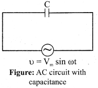
$V_m \sin \omega t$......(1)
Let $q$ be the instantaneous charge on the capacitor. The emf across the capacitor at that instant is $\frac{q}{C}$. According to Kirchoff's loop rule,.
$u =\frac{q}{C}=0$
$\Rightarrow C V _{ m } \sin \omega t$
By the definition of current,
$i =\frac{d q}{d t}=\frac{d}{d t} CV _{ m } \frac{d}{d t}(\sin \omega t )$
$= CV _{ m } \sin \omega t$
$\text { or } i =\frac{\frac{ v _m}{1}}{\frac{1}{ C _\omega}} \sin \left(\omega t+\frac{\pi}{2}\right)$
$i = I _{ m } \sin \left(\omega t+\frac{\pi}{2}\right) \ldots . .(2)$
where $\frac{\frac{ v _m}{1}}{\frac{1}{ C _\omega}}=I_{ m }$, the peak value of the alternating current. From equation (1) and (2), it is clear that current leads the applied voltage by $\pi / 2$ in a capacitive circuit. The wave diagram for a capacitive circuit also shows that the current leads the applied voltage by $90^{\circ}$.
Consider a circuit containing a capacitor of capacitance C connected across an alternating voltage source.
The alternating voltage is given by
$V_m \sin \omega t$......(1)
Let $q$ be the instantaneous charge on the capacitor. The emf across the capacitor at that instant is $\frac{q}{C}$. According to Kirchoff's loop rule,.
$u =\frac{q}{C}=0$
$\Rightarrow C V _{ m } \sin \omega t$
By the definition of current,
$i =\frac{d q}{d t}=\frac{d}{d t} CV _{ m } \frac{d}{d t}(\sin \omega t )$
$= CV _{ m } \sin \omega t$
$\text { or } i =\frac{\frac{ v _m}{1}}{\frac{1}{ C _\omega}} \sin \left(\omega t+\frac{\pi}{2}\right)$
$i = I _{ m } \sin \left(\omega t+\frac{\pi}{2}\right) \ldots . .(2)$
where $\frac{\frac{ v _m}{1}}{\frac{1}{ C _\omega}}=I_{ m }$, the peak value of the alternating current. From equation (1) and (2), it is clear that current leads the applied voltage by $\pi / 2$ in a capacitive circuit. The wave diagram for a capacitive circuit also shows that the current leads the applied voltage by $90^{\circ}$.
Question 35 Marks
Find out the phase relationship between voltage and current in a pure resister circuit.
Answer
View full question & answer→$AC$ circuit containing pure resistor:
Consider a circuit containing a pure resistor of resistance $R$ connected across an alternating voltage source. The instantaneous value of the alternating voltage is given by
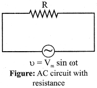
$u = V _{ m } \sin \omega t$
An alternating current i flowing in the circuit due to this voltage, develops a potential drop across $R$ and is given by
$V _{ R }= iR$
Kirchoff's loop rule states that the algebraic sum of potential differences in a closed circuit is zero. For this resistive circuit,
$u-V_R=0$
From equation (1) and (2),
$V_m \sin \omega t=i R$
$\Rightarrow i =\frac{V_m}{R} \sin \omega t$
$i = I _{ m } \sin \omega t \ldots \ldots .$
$u = V _{ m } \sin \omega t$
An alternating current i flowing in the circuit due to this voltage, develops a potential drop across $R$ and is given by
$V _{ R }= iR.......(2)$
Kirchoff's loop rule states that the algebraic sum of potential differences in a closed circuit is zero. For this resistive circuit,
$u-V_R=0$
From equation (1) and (2),
$V_m \sin \omega t=i R$
$\Rightarrow i =\frac{V_m}{R} \sin \omega t$
$i = I _{ m } \sin \omega t \ldots \ldots (3)$
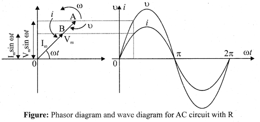
where $V \frac{V_m}{R}= I _{ m }$ the peak value of alternating current in the circuit. From equations (1) and and (3), it is clear that the applied voltage and the current are in phase with each other in a resistive circuit. It means that they reach their maxima and minima simultaneously. This is indicated in the phasor diagram. The wave diagram also depicts that current is in phase with the applied voltage.
Consider a circuit containing a pure resistor of resistance $R$ connected across an alternating voltage source. The instantaneous value of the alternating voltage is given by
$u = V _{ m } \sin \omega t$
An alternating current i flowing in the circuit due to this voltage, develops a potential drop across $R$ and is given by
$V _{ R }= iR$
Kirchoff's loop rule states that the algebraic sum of potential differences in a closed circuit is zero. For this resistive circuit,
$u-V_R=0$
From equation (1) and (2),
$V_m \sin \omega t=i R$
$\Rightarrow i =\frac{V_m}{R} \sin \omega t$
$i = I _{ m } \sin \omega t \ldots \ldots .$
$u = V _{ m } \sin \omega t$
An alternating current i flowing in the circuit due to this voltage, develops a potential drop across $R$ and is given by
$V _{ R }= iR.......(2)$
Kirchoff's loop rule states that the algebraic sum of potential differences in a closed circuit is zero. For this resistive circuit,
$u-V_R=0$
From equation (1) and (2),
$V_m \sin \omega t=i R$
$\Rightarrow i =\frac{V_m}{R} \sin \omega t$
$i = I _{ m } \sin \omega t \ldots \ldots (3)$
where $V \frac{V_m}{R}= I _{ m }$ the peak value of alternating current in the circuit. From equations (1) and and (3), it is clear that the applied voltage and the current are in phase with each other in a resistive circuit. It means that they reach their maxima and minima simultaneously. This is indicated in the phasor diagram. The wave diagram also depicts that current is in phase with the applied voltage.
Question 45 Marks
How will you define the unit of mutual-inductance?
Answer
View full question & answer→"Unit of mutual inductance:
The unit of mutual inductance is also henry $(H)$.
If $i _{ A }=1 A$ and $N _2 \Phi_{21}=1 Wb$ turns, then $M _{21}=1 H$.
Therefore, the mutual inductance between two coils is said to be one henry if a current of $1 A$ in coil 1 produces unit flux linkage in coil 2. If $\frac{d i_1}{2}=1 As ^{-1}$ and $\varepsilon_2=-1 V$, theen $M _{21}=1 H$.
Therefore, the mutual inductance between two coils is one henry if a current changing at the rate of IAs-1 in coil 1 induces an opposing emf of IV in coil 2."
Question 55 Marks
Derive an expression for Mutual Inductance between two long co-axial solenoids.
Answer
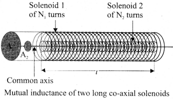
View full question & answer→Mutual inductance between two long co-axial solenoids:
Consider two long co-axial solenoids of same length 1. The length of these solenoids is large when compared to their radii so that the magnetic field produced inside the solenoids is uniform and the fringing effect at the ends may be ignored. Let $A_1$ and $A_2$ be the area of cross section of the solenoids with $A_1$ being greater than $A_2$. The turn densities of these solenoids are $n_1$ and $n_2$ respectively.
Let $i_1$ be the current flowing through solenoid 1 , then the magnetic field produced inside it is
$B _1=\mu_0 n _1 i _1 \text {. }$
As the field lines of $\overrightarrow{B_1}$ are passing through the area bounded by solenoid 2, the magnetic flux is linked with each turn of solenoid 2 due to solenoid 1 and is given by
$\phi_{21}=\int_{ A _2} \overrightarrow{ B _1} \cdot d \overrightarrow{ A }= B _1 A _2=\left(\mu_0 n_1 i_1\right) A _2$
since $\theta=0^{\circ}$
The flux linkage of solenoid 2 with total turns $N _2$ is
$N_2 \Phi_{21}=\left(n_2 l\right)\left(\mu_0 n_1 i_1\right)$
$\text { since } N_2=n_2 l$
$N_2 \Phi_{21}=\left(\mu_0 n_1 n_2 A_2 l\right) i_1$
From equation of mutual induction
$N _2 \Phi_{21}= M _{21} i _1$
Comparing the equations (1) and (2),
$M _{21}=\mu_0 n _1 n _2 A _2 l$
This gives the expression for mutual inductance $M_{21}$ of the solenoid 2 with respect to solenoid 1 . Similarly, we can find mutual inductance $M_{21}$ of solenoid 1 with respect to solenoid 2 as given below.
The magnetic field produced by the solenoid 2 when carrying a current $i_2$ is
$B _2=\mu_0 n _2 i _2$
This magnetic field $B_2$ is uniform inside the solenoid 2 but outside the solenoid 2, it is almost zero. Therefore for solenoid 1 , the area $A_2$ is the effective area over which the magnetic field $B_2$ is present; not area $A_2$ Then the magnetic flux $\Phi_{12}$ linked with each turn of solenoid 1 due to solenoid 2 is
$\Phi_{12}=\int_{ A _2} \overrightarrow{ B _2} \cdot d \overrightarrow{ A }= B _2 A _2=\left(\mu_0 n_2 i_2\right) A _2$
The flux linkage of solenoid 1 with total turns $N_1$ is
[Since $N _1= n _1$ l]
[Since $N _1 \Phi_{12}= M _{12} i _2$ ]
$N _1 \Phi_{12}=\left( n _1 l\right)\left(\mu_0 n _2 i _2\right) A _2$
$N_1 \Phi_{12}=\left(\mu_0 n_1 n_2 A_2 l\right) i_2$
$M _{12} i _2=\left(\mu_0 n _1 n _2 A _2 l\right) i _2$
Therefore, we get
$\therefore M _{12}=\mu_0 n _1 n _2 A _2 l$
From equation (3) and (4), we can write
$M _{12}= M _{21}= M$
In general, the mutual inductance between two long co-axial solenoids is given by
$M =\mu_0 n _1 n _2 A _2 l$
If a dielectric medium of relative permeability' pr is present inside the solenoids, then
$M=\mu n_1 n_2 A_2 l$
or $M =\mu_0 \mu_{ r } n _1 n _2 A _2 I$