Questions

2 Marks Questions

Take a timed test

19 questions · self-marked practice — reveal the answer and mark yourself.

Question 12 Marks
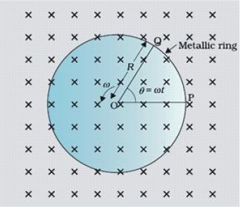
A 1.0m long metallic rod is rotated with an angular frequency of 400 rad $s^{-1}$ about an axis normal to the rod passing through its one end. The other end of the rod is in contact with a circular metallic ring. A constant and uniform magnetic field of 0.5T parallel to the axis exists everywhere. Calculate the emf developed between the centre and the ring.
Answer
Length of the rod, l = 1m
Angular frequency, $\omega=400\text{ rad/s}$
Magnetic field strength, B = 0.5T
One end of the rod has zero linear velocity, while the other end has a linear velocity of $\text{l}\omega.$
Average linear velocity of the rod, $\text{v}=\frac{\text{l}\omega+0}{2}=\frac{\text{l}\omega}{2}$
Emf developed between the centre and the ring,
$\text{e}=\text{Blv}=\text{Bl}\Big(\frac{\text{l}\omega}{2}\Big)=\frac{\text{B}\text{l}^2\omega}{2}$
$=\frac{0.5\times(1)^2\times400}{2}=100\text{V}$
Hence, the emf developed between the centre and the ring is 100V.
View full question & answer
Question 22 Marks
Current in a circuit falls from 5.0A to 0.0A in 0.1s. If an average emf of 200V induced, give an estimate of the self-inductance of the circuit.
Answer
Initial current, $\mathrm{I}_1=5.0 \mathrm{~A}$
Final current, $\mathrm{I}_2=0.0 \mathrm{~A}$
Change in current, $\mathrm{dl}=\mathrm{I}_1-\mathrm{I}_2=5 \mathrm{~A}$
Time taken for the change, $t = 0.1s$
Average emf, $e = 200V$
For self-inductance (L) of the coil, we have the relation for average emf as:
$\text{e}=\text{L}\frac{\text{di}}{\text{dt}}$
$\text{L}=\frac{\text{e}}{\Big(\frac{\text{di}}{\text{dt}}\Big)}$
$=\frac{200}{\frac{5}{0.1}}=4\text{H}$
Hence, the self induction of the coil is 4H.
View full question & answer
Question 32 Marks
Use Lenz’s law to determine the direction of induced current in the situations described by Fig.
  1. A wire of irregular shape turning into a circular shape;
  1. A circular loop being deformed into a narrow straight wire.
Answer
According to Lenz's law, the direction cf the induced emf is such that it tends to produce a current that opposes the change in the magnetic flux that produced it.
  1. When the shape of the wire changes, the flux piercing through the unit surface area increases. As a result, the induced current produces an opposing flux. Hence, the induced current flows along adcb.
  2. When the shape of a circular loop is deformed into a narrow straight wire, the flux piercing the surface decreases. Hence, the induced current flows along
$\text{e}=\frac{4\pi\times10^{-7}\times50\times0.1\times10}{2\pi\times0.2}$

$e = 5 × 10^{-5}\ V a'd'c'b'.$
View full question & answer
Question 42 Marks
State the underlying principle of a transformer.How is the large scale transmission of electric energy over long distances done with the use of transformers?
Answer
A transformer is based on principle of mutual induction which states that due to continuous change in the current in the primary coil, an emf gets induced across the secondary coil.
Electric power generated at the power station, is stepped up to very high voltages by means of a step-up transformer and transmitted to a distant place. At receiving end, it is stepped down by a step down transformer.
View full question & answer
Question 52 Marks
What are eddy currents? Write any two applications of eddy currents.
Answer
When a bulk piece of conductor is subjected to changing magnetic flux, the induced currents, developed in it is called Eddy current.
uses:
  • Magnetic brakes in trains.
  • Electromagnetic damping.
  • Induction furnaces.
  • Electric power meter.
  • Induction therapy.
  • To find the melting point of precious metals.
  • In speedometer of vehicles.
View full question & answer
Question 62 Marks
Two identical loops, one of copper and the other of aluminium, are rotated with the same angular speed in the same magnetic field. Compare (i) the induced emf and (ii) the current produced in the two coils. Justify your answer.
Answer
  1. Emf produced in two coils is same because it depends only on the rate of change of magnetic flux which is same for both the loops.
  2. Current in copper loop is more because resistivity/resistance of copper is less. (I=V/R).
View full question & answer
Question 72 Marks
The circuit arrangement given below shows that when an a.c. passes through the coil A, the current starts flowing in the coil B.
  1. State the underlying principle involved.
  2. Mention two factors on which the current produced in the coil B depends.
Answer
  1. Electromagnetic Induction/Mutual Induction.
  2. Rate of change of flux/number of turns/cross-section area/relative separation/core material/load resistance.
View full question & answer
Question 82 Marks
A light bulb and a solenoid are connected in series across an ac source of voltage. Explain, how the glow of the light bulb will be affected when an iron rod is inserted in the solenoid.
Answer
Brightness decreases.
Explanation:- Self inductance of solenoid increases; this increases the impedance of the circuit and hence current decreases.
View full question & answer
Question 92 Marks
State Lenz’s Law.
A metallic rod held horizontally along east-west direction, is allowed to fall under gravity. Will there be an emf induced at its ends? Justify your answer.
Answer
The polarity of induced emf is such that it tends to produce a current which opposes the change in magnetic flux that produced it.
Yes, as the magnetic flux due to vertical component of Earth’s magnetic keeps on changing as the metallic rod falls down.
View full question & answer
Question 102 Marks
A metallic rod of 'L' length is rotated with angular frequency of '$\omega$' with one end hinged at the centre and the other end at the circumference of a circular metallic ring of radius L, about an axis passing through the centre and perpendicular to the plane of the ring. A constant and uniform magnetic field B parallel to the axis is present everywhere. Deduce the expression for the emf between the centre and the metallic ring.
Answer

The magnitude of the emf, generated across a length dr of the rod, as it moves at right angles to the magnetic field, is given by
$\text{d}\varepsilon = \text{B}v\text{dr}.$
Therefore
$\varepsilon = \int\text{d}\varepsilon = \int\limits_{0}^{\text{R}}\text{B}v\text{dr} = \int\limits_{0}^{\text{R}}\text{B}\omega\text{rdr} =\frac{\text{B}\omega\text{R}^{2}}{2}.$
Alternate Answer
The potential difference across there sistor is equal to the induced emf and equals B× (rate of change of area of loop). If $\theta$is the angle between the rod and the radius of the circle at P at time t, the area of the sector OPQ(as shown in the figure) is given by
$\pi\text{R}^{2}\times\frac{\theta}{2\pi} = \frac{1}{2}\text{R}^{2}\theta$
Where R is the radius of the circle. Hence, the induced emf is $\varepsilon = \text{B} \times\frac{\text{d}}{\text{dt}}\bigg[ = \frac{1}{2}\text{R}^{2}\theta\bigg] = \frac{1}{2}\text{BR}^{2}\frac{\text{d}\theta}{\text{dt}} =\frac{\text{B}\omega\text{R}^{2}}{2}.$
View full question & answer
Question 112 Marks
Define self-inductance of a coil. Show that magnetic energy required to build up the current I in a coil of self inductance L is given by $\frac{1}{2}\text{LI}^{2}.$
Answer
Self Inductance is the property by which an opposing induced emf is produced in a coil due to a change in current, or magnetic flux, linkedwith the coil.
Alternate Answer
Self inductance of a coil is numerically equal to the flux linked with the coil when the current through the coil is 1A.

Alternate Answer
self inductance of a coil is equal to the induced emf developed in the coil when the rate of change of current is the coil is one ampere per second.
Energy stored in an inductor:
Consider a source of emf connected to an inductor L.As the current starts growing, the opposing induced emf is given by
$\text{e} = -\text{L}\frac{\text{di}}{\text{dt}}$
If the source of emf sends a current i through the inductor for a small time dt, then the amount of work, done by the source, is given by
$\text{dW} = |\text{e}|\text{i}\text{ dt}$
$ = \text{Li}\frac{\text{di}}{\text{dt}}\text{dt}$
$ = \text{Lidi}$
Hence the total amount of work done (by the source of emf) will the current increases from its initial value (i = 0) to its final value (I) is given by
$\text{W} = \int\limits_{0}^{i}\text{Lidi} = \text{L}\int\limits_{0}^{i}\text{idi} =\text{L}\bigg[\frac{\text{i}^{2}}{2}\bigg] = \frac{1}{2}\text{Li}^{2}$
This work done gets stored in the inductor in the form of energy.
$\therefore\text{U} = \frac{1}{2}\text{Li}^{2}.$
View full question & answer
Question 122 Marks
A current is induced in coil $C_1$ due to the motion of current carrying coil $C_2$. (a) Write any two ways by which a large deflection can be obtained in the galvanometer G. (b) Suggest an alternative device to demonstrate the induced current in place of a galvanometer.
Answer
Any two ways to obtain large deflection in G
Moving $C_2$ faster towards $C_1$ / Increasing current in $C_2 /$
Insertion of soft iron core in $\mathrm{C}_1 /$
Increasing number of turns of $\mathrm{C}_1 /$
Increasing area of cross section of $\mathrm{C}_1$
Alternative device
Bulb/LED/Compass needle/any other device responsive to (small) current.
View full question & answer
Question 132 Marks
Show diagrammatically when is magnetic flux taken as:
  1. Positive.
  2. Negative.
Answer
  1. f the normal N to area A is in the same direction to B,
$\text{f}=\vec{\text{B}}.\vec{\text{A}}\text{ is positive}.$
  1. If the normal N is in the opposite direction to B.
$\phi=\cos180^{\circ}\text{is negative.}$
View full question & answer
Question 142 Marks
Figure. shows two positions of a loop PQR in a perpendicular uniform magnetic field. In which position of the coil is there an induced emf?
Answer
  1. The coil remains as such in magnetic field, so there is no magnetic flux change in the coil, hence no emf is induced.
  2. The coil is coming out of the magnetic field, so the magnetic flux linked with it decreases and so an emf is induced in the coil.
View full question & answer
Question 152 Marks
The battery discussed in the previous question is suddenly disconnected. Is a current induced in the other loop? If yes, when does it start and when does it end? Do the loops attract each other or repel?
Answer
As the battery is disconnected the current starts decreasing in lop 1 and thus now direction of current is in opposite direction as it was earlier and it ends when both loops are in equilibrium.
View full question & answer
Question 162 Marks
An inductor is connected to a battery through a switch. Explain why the emf induced in the inductor is much larger when the switch is opened as compared to the emf induced when the switch is closed.
Answer
Due to self inductance the emf produced when circuit is open the growth of current in inductor is small but when switch is closed the decay in current is faster thus emf induced is more.
View full question & answer
Question 172 Marks
Two coils of wire A and B are placed mutually perpendicular as shown in figure. When current is changed in any one coil, will the current induce in another coil?
Answer
No, this is because the magnetic field due to current in coil (A or B) will be parallel to the plane of the other coil (A or B) Hence, the magnetic flux linked with the other coil will be zero and so no current will be induced in it.
View full question & answer
Question 182 Marks
Derive an expression for (i) induced emf and (ii) induced current when a conductor of length l is moved with a uniform velocity, normal to a uniform magnetic field B. Assume the resistance of conductor to be R.
Answer
Expression for Induced emf: We know that if a charge q moves with velocity $\vec{\text{v}}$ in a magnetic field of strength $\vec{\text{B}},$ making an angle θ then magnetic Lorentz force:$\text{F} = \text{qvB} \sin \theta$
If $\vec{\text{v}}$ and $\vec{\text{B}}$ mutually perpendicular, then $\theta=90^{\circ}$
$​​\text{F}=\text{qvB}\sin90^{\circ}=\text{qvB}$
The direction of this force is perpendicular to both $\vec{\text{v}}$ and $\vec{\text{B}}$ and is given by Fleming’s left hand rule. Suppose a thin conducting rod PQ is placed on two parallel metallic rails CD and MN in a magnetic field of strength $\vec{\text{B}}$ The direction of magnetic field $\vec{\text{B}}$ is represented by cross (×) marks. Suppose the rod is moving with velocity $\vec{\text{v}}$ perpendicular to its own length, towards the right. We know that metallic conductors contain free electrons, which can move within the metal. As charge on electron, q = -e therefore, each electron experiences a magnetic Lorentz force, Fm = evB, whose direction, according to Fleming’s left hand rule, will be from P to Q Thus the electrons are displaced from end P towards end Q Consequently the end P of rod becomes positively charged and end Q negatively charged. Thus a potential difference is produced between the ends of the conductor. This is the induced emf.
Due to induced emf, an electric field is produced in the conducting rod. The strength of this electric field:
$\text{E}=\frac{\text{V}}{\text{l}}\dots{(\text{i}})$
And its direction is from (+) to (-) charge, i.e., from P to Q.
The force on a free electron due to this electric field, Fe = eE ...(ii)
The direction of this force is from Q to P which is opposite to that of electric field. Thus the emf produced opposes the motion of electrons caused due to Lorentz force. This is in accordance with Lenz’s law. As the number of electrons at end becomes more and more, the magnitude of electric force Fe goes on increasing, and a stage comes when
electric force and magnetic force $\overrightarrow{\text{Fe}}$ and magnetic force $\overrightarrow{\text{Fm}}$ become equal and opposite. In this situation the potential difference produced across the ends of rod becomes constant. In this condition.
Fe = Fm
eE = evB or E = Bv ...(iii)
The potential difference produced,
V = El = B × v × l × Volt
Also the induced current $\text{I}=\frac{\text{V}}{\text{R}}=\frac{\text{Bvl}}{\text{R}}\text{ ampere}$
View full question & answer
Question 192 Marks
Consider Experiment 6.2. (a) What would you do to obtain a large deflection of the galvanometer? (b) How would you demonstrate the presence of an induced current in the absence of a galvanometer?
Answer
(a) To obtain a large deflection, one or more of the following steps can be taken: (i) Use a rod made of soft iron inside the coil $C_2$, (ii) Connect the coil to a powerful battery, and (iii) Move the arrangement rapidly towards the test coil $C_1$.
(b) Replace the galvanometer by a small bulb, the kind one finds in a small torch light. The relative motion between the two coils will cause the bulb to glow and thus demonstrate the presence of an induced current.
In experimental physics one must learn to innovate. Michael Faraday who is ranked as one of the best experimentalists ever, was legendary for his innovative skills.
View full question & answer