- A parallel plate capacitor $(C_1)$ having charge Q is connected, to an identical uncharged capacitor $C_2$ in series. What would be the charge accumulated on the capacitor $C_2?$
- Three identical capacitors each of capacitance 3mF are connected, in tern, in series and in parallel combination to the common source of V volt. Find out the ratio of the energies stored in two configurations.
CBSE OUTSIDE DELHI - SET 1 SOUTH 2016
Download our app for free and get started
- Zero.
- We have $\text{C}_{series} = \frac{3\mu\text{F}}{3} =1 \mu\text{F}$
Energy stored $ = \frac{1}{2}\text{CV}^{2}$
$\therefore$Energy in series combination $ =\frac{1}{2}1 \times10^{-6}\times\text{V}^{2}$
Energy in parallel combination $ =\frac{1}{2}9 \times10^{-6}\times\text{V}^{2}$
$\therefore$ Ratio = 1:9.

Download our appand get started for free
Experience the future of education. Simply download our apps or reach out to us for more information. Let's shape the future of learning together!No signup needed.*
Similar Questions
- 1Two capacitors of capacitance $10\mu\text{F}$ and $20 \mu\text{F}$ are connected in series with a 6 V battery. After the capacitors are fully charged, a slab of dielectric constant (K) is inserted between the plates of the two capacitors. How will the following be affected after the slab is introduced:View Solution
- The electric field energy stored in the capacitors.
- The charges on the two capacitors.
- The potential difference between the plates of the capacitors.
- 2View SolutionState Lenz’s law. Illustrate, by giving an example, how this law helps in predicting the direction of the current in a loop in the presence of a changing magnetic flux.
In a given coil of self-inductance of 5 mH, current changes from 4 A to 1 A in 30 ms. Calculate the emf induced in the coil. - 3View SolutionA series LCR circuit is connected to an ac source. Using the phasor diagram, derive the expression for the impedance of the circuit. Plot a graph to show the variation of current with frequency of the source, explaining the nature of its variation.
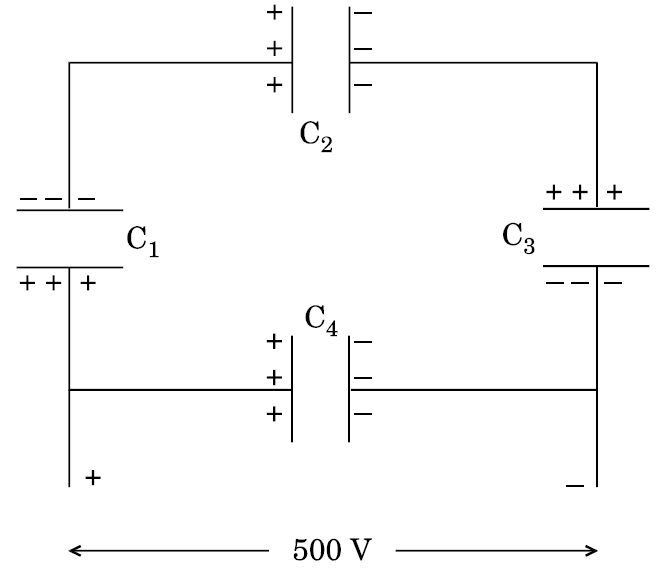
- 4A network of four 10 $\mu$F capacitors is connected to a 500 V supply as shown in the figure. Determine theView Solution
- equivalent capacitance of the network and
- charge on each capacitor
- 5View SolutionIn the given diagram, a coil B is connected to low voltage bulb L and placed parallel to another coil A as shown. Explain the following observations:
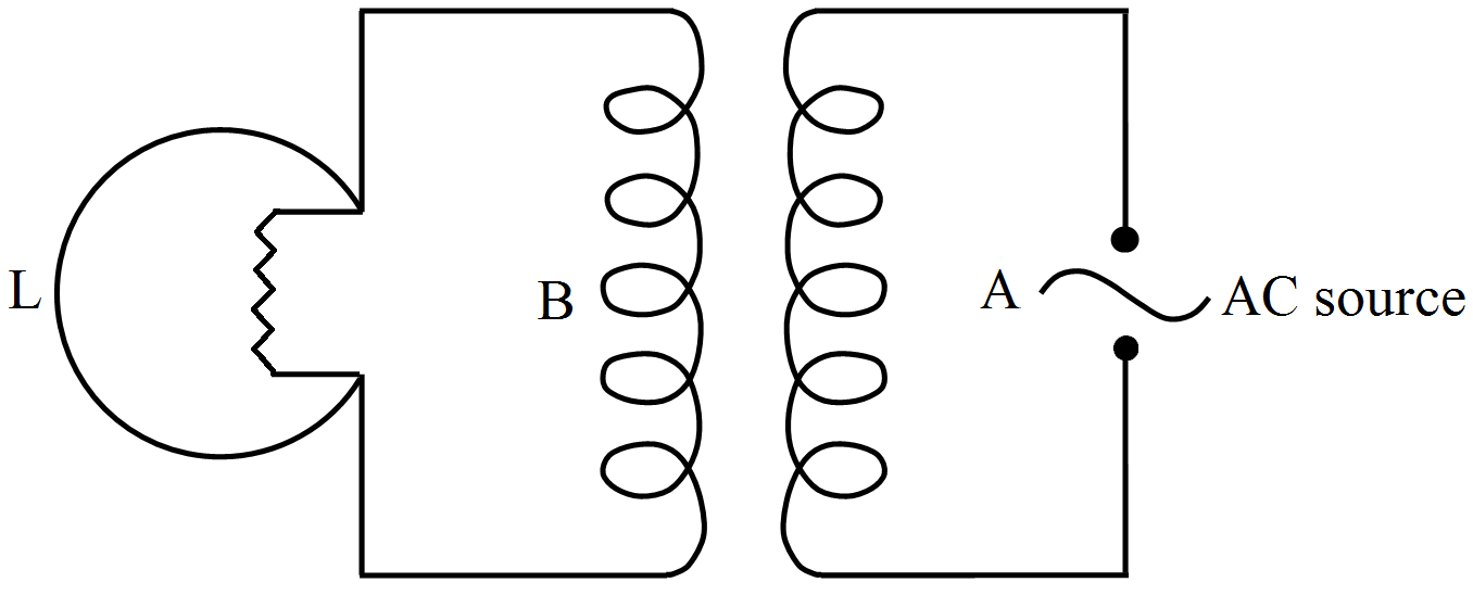
- Bulb lights.
- Bulb gets dimmer if the coil B moves upwards.
- 6Two identical cells of emf 1.5 V each joined in parallel supply energy to an external circuit consisting of two resistances of 7 $\Omega$ each joined in parallel. A very high resistance voltmeter reads the terminal voltage of cells to be 1.4 V. Calculate the internal resistance of each cell.View Solution
- 7View SolutionFigure shows a light bulb (B) and iron cored inductor connected to a dc battery through a switch (S).
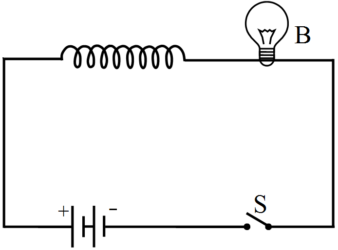
- What will one observe when switch (S) is closed?
- How will the glow of the bulb change when the battery is replaced by an ac source of rms voltage equal to the voltage of dc battery? Justify your answer in each case.
- 8A capacitor of unknown capacitance, a resistor of 100 $\Omega$ and an inductor of self inductance L = $( 4 /\pi^{2})$henry are connected in series to an ac source of 200V and 50 Hz. Calculate the value of the capacitance and impedance of the circuit when the current is in phase with the voltage. Calculate the power dissipated in the circuit.View Solution
- 9View SolutionA transformer has 50 turns in the primary and 100 in the secondary. If the primary is connected to a 220V DC supply, what will be the voltage across the secondary?
- 10View Solution
- Distinguish between a conductor and a semi conductor on the basis of energy band diagram.
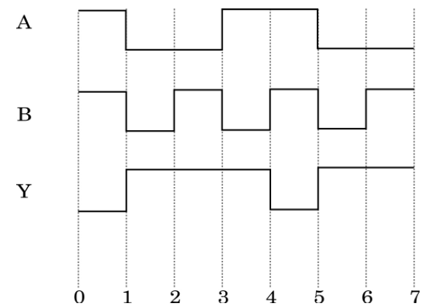
- The following figure shows the input waveforms (A, B) and the output waveform (Y) of a gate. Identify the gate, write its truth table and draw its logic symbol.