A steel wire has a resistance twice that of an aluminium wire. Both of them are connected with a constant voltage supply. More heat will be dissipated in
Easy
Download our app for free and get started
(d) ${R_{steel}} = 2{R_{Al}}$. In series $H \propto R$ ($i$ is Same)
So, $H$ will be more in steel wire . In parallel $H \propto \frac{1}{R}$ ($V$ is Same), so $H$ will be more in aluminium wire.

Download our appand get started for free
Experience the future of education. Simply download our apps or reach out to us for more information. Let's shape the future of learning together!No signup needed.*
Similar Questions
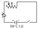
- 1The battery in the diagram is to be charged by the generator $G$. The generator has a terminal voltage of $120$ $\mathrm{volts}$ when the charging current is $10$ $\mathrm{amperes}.$ The battery has an $\mathrm{emf}$ of $100$ $\mathrm{volts}$ and an internal resistance of $1$ $\mathrm{ohm}.$ In order to charge the battery at $10$ $\mathrm{amperes}$ charging current, the resistance $R$ should be set at ................ $\Omega$View Solution
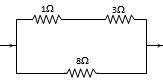
- 2Power dissipated across the $8 \,\,\Omega$ resistor in the circuit shown here is $2\,\, watt.$ The power dissipated in watt units across the $3 \,\,\Omega$ resistor isView Solution
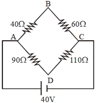
- 3Four resistances $40 \ \Omega, 60\ \Omega, 90\ \Omega$ and $110\ \Omega$ make the arms of a quadrilateral $A,B,C,D$. Across $AC$ is a battery of emf $40\, V$ and internal resistance negligible. The potential difference across $BD$ is $V$ is......View Solution
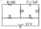
- 4In the circuit shown, the cell is ideal, with $emf$ $=$ $15$ $V$. Each resistance is of $3 $ $\Omega$ . The potential difference across the capacitor is.....$V$View Solution
- 5When a current of $2\, A$ flows in a battery from negative to positive terminal, the potential difference across it is $12\, V$. If a current of $3 \,A$ flows in the opposite direction potential difference across the terminals of the battery is $15\, V$, the $emf$ of the battery is ................ $\mathrm{V}$View Solution
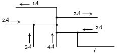
- 6The figure here shows a portion of a circuit. What are the magnitude and direction of the current i in the lower right-hand wire .................... $A$View Solution
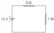
- 7In the following circuit, $1 \,\Omega$ resistor dissipates power $P$. If the resistor is replaced by $9 \,\Omega$, the power dissipated in it isView Solution
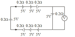
- 8The reading in the ideal voltmeter $(V)$ shown in the given circuit diagram is :View Solution
- 9A student is provided with a variable voltage source $V$, a test resistor $R_T=10\,\Omega$, two identical galvanometers $G_1$ and $G_2$ and two additional resistors, $R _1=10\,M\,\Omega$ and $R _2=0.001\,\Omega$. For conducting an experiment to verify ohms law, the most suitable circuit is:View Solution
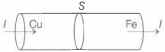
- 10Two rods of copper and iron with the same cross-sectional area are joined at $S$ and a steady current $I$ flows through the rods as shown in the figure. Choose the most appropriate representation of charges accumulated near the junction $S$.View Solution