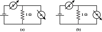
A student uses the resistance of a known resistor $(1 \,\Omega)$ to calibrate a voltmeter and an ammeter using the circuits shown below. The student measures the ratio of the voltage to current to be $1 \times 10^3 \,\Omega$ in circuit $(a)$ and $0.999 \,\Omega$ in circuit $(b)$. From these measurements, the resistance (in $\Omega$ ) of the voltmeter and ammeter are found to be close to
KVPY 2019, Advanced
Download our app for free and get started
(b)
When a voltmeter put in series, it still reads potential drop and when an ammeter is connected in parallel, it still shows current through it.
Let $I=$ current through cell, then potential drop read by voltmeter is $V=I \cdot R_V$ (this is reading of voltmeter)
Where, $R_V$ is the resistance of voltmeter In $\operatorname{loop} A B$,
$V_{A B}=I_1 \times 1=I_2 \times R_A$ and $I=I_1+I_2$
Where, $R_A$ is the resistance of ammeter We substitute for $I_1$ from above equation to get
$\Rightarrow \quad I=I_2 R_A+I_2=I_2\left(R_A+1\right)$
$\Rightarrow \quad I_2=\frac{I}{\left(R_A+1\right)}$
(this is reading of ammeter)
Now given, voltmeter reading ammeter reading $=1 \times 10^3=\frac{I R_V}{\left(\frac{I}{R_A+1}\right)}$
So, $R_V\left(R_A+1\right)=1000 \dots(i)$
Let $I=$ current through cell, then ammeter reading in this case is $I$.
Also, in loop $A B$,
$V_{A B}=I_1 \times 1=I_2 \times R_V$
$\text { As, } I=I_1+I_2=I_2 R_V+I_2$
$=I_2\left(R_V+1\right)$
So, $I_2=\frac{I}{\left(R_V+1\right)}$
Hence, voltmeter reading is $V=I_2 R_V$
$=\frac{I R_V}{\left(R_V+1\right)}$ (this is reading of voltmeter)
Now given, voltmeter reading $\div$ ammeter reading $=0.999 \,\Omega$.
So, $0.999=\left[\frac{I_V}{\left(R_V+1\right)}\right]$
$\Rightarrow 0.999=\frac{R_V}{R_V+1}$
So, $R_V=999 \,\Omega \dots(ii)$
$=10^3 \Omega$
Substituting $R_V$ in Eq $(i)$, we get
$R_A=\frac{1}{999}$
$\text { or } R_A=10^{-3} \,\Omega$

Download our appand get started for free
Experience the future of education. Simply download our apps or reach out to us for more information. Let's shape the future of learning together!No signup needed.*
Similar Questions
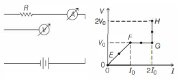
- 1In the circuit shown below (on the left) the resistance and the emf source are both variable. The graph of seven readings of the voltmeter and the ammeter ( $V$ and $I$, respectively) for different settings of resistance and the emf, taken at equal intervals of time $\Delta t$, are shown below (on the right) by the dots connected by the curve $E F G H$. Consider the internal resistance of the battery to be negligible and the voltmeter an ammeter to be ideal devices. (Take, $R_0 \equiv \frac{V_0}{I_0}$ ).View Solution
Then, the plot of the resistance as a function of time corresponding to the curve $E F G H$ is given by
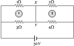
- 2Current through wire $XY$ of circuit shown is ................ $A$View Solution
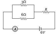
- 3If the ammeter in the given circuit reads $2\, A$, the resistance $R$ is ............ $ohm$View Solution
- 4Tend identical cells each of potential $E$ and internal resistance $r$ are connected in series to form a closed circuit. An ideal voltmeter connected across three cells, will read $...........E$View Solution
- 5The potential gradient along the length of a uniform wire is $10\,volt/metre$. $B$ and $C$ are the two points at $30\,cm$ and $60\,cm$ point on a meter scale fitted along the wire. The potential difference between $B$ and $C$ will be ............. $volt$View Solution
- 6Column $- I$ gives certain physical terms associated with flow of current through a metallic conductor. Column $- II$ gives some mathematical relations involving electrical quantities. Match Column $- I$ and Column $- II$ with appropriate relations.View Solution
Column $- I$ Column $- II$ $(A)$ Drift Velocity $(P)$ $\frac{m}{n e^{2} \rho}$ $(B)$ Electrical Resistivity $(Q)$ $\mathrm{ne} v_{\mathrm{d}}$ $(C)$ Relaxation Period $(R)$ $\frac{\mathrm{eE}}{\mathrm{m}} \tau$ $(D)$ Current Density $(S)$ $\frac{E}{J}$ - 7The current in a simple series circuit is $5.0\, amp$. When an additional resistance of $2.0\, ohms$ is inserted, the current drops to $4.0\, amp$. The original resistance of the circuit in $ohms$ wasView Solution
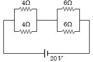
- 8Four resistances are connected in a circuit in the given figure. The electric current flowing through $4\, ohm$ and $6\, ohm$ resistance is respectivelyView Solution
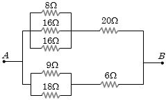
- 9The equivalent resistance of the arrangement of resistances shown in adjoining figure between the points $A$ and $B$ is ............... $ohm$View Solution
- 10View SolutionIn the circuit diagram shown below, the magnitude and direction of the flow of current respectively would be