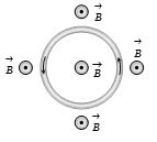
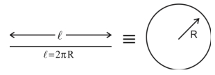
An elastic circular wire of length $l$ carries a current $I$. It is placed in a uniform magnetic field $\mathop B\limits^ \to $ (Out of paper) such that its plane is perpendicular to the direction of $\mathop B\limits^ \to $. The wire will experience
Easy


Download our appand get started for free
Experience the future of education. Simply download our apps or reach out to us for more information. Let's shape the future of learning together!No signup needed.*
Similar Questions
- 1An insulating rod of length $l$ carries a charge $q$ distributed uniformly on it. The rod is pivoted at an end and is rotated at a frequency $f$ about a fixed perpendicular $t$ axis. The magnetic moment of the system isView Solution
- 2The coil in a moving coil galvanometer experiences torque proportional to current passes through it. If a steady current $i$ is passed through it the steady deflection of the coil is found to be $90^o$ . Now the steady current is switched off and a charge $q$ is suddenly passed through coil. If the coil has $N$ turns of area $A$ and its moment of inertia is $I$ about the axis it is going to rotate then the maximum angle through which it deflects upon passing charge $q$ isView Solution
- 3A hairpin like shape as shown in figure is made by bending a long current carrying wire. What is the magnitude of a magnetic field at point $P$ which lies on the centre of the semicircle ?View Solution

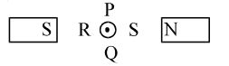
- 4View SolutionA straight current carrying conductor is placed in such a way that the current in the conductor flows in the direction out of the plane of the paper. The conductor is placed between two poles of two magnets, as shown. The conductor will experience a force in the direction towards
- 5A wire of length $314\,cm$ carrying current of $14\,A$ is bent to form a circle. The magnetic moment of the coil is $........A- m ^{2}$. [Given $\left.\pi=3.14\right]$View Solution
- 6The circuit in figure consists of wires at the top and bottom and identical springs as the left and right sides. The wire at the bottom has a mass of $10\, g$ and is $5\, cm$ long. The wire is hanging as shown in the figure. The springs stretch $0.5\, cm$ under the weight of the wire and the circuit has a total resistance of $12\, \Omega $. When the lower wire is subjected to a static magnetic field, the springs, stretch an additional $0.3\, cm$. The magnetic field isView Solution

- 7A thin circular wire carrying a current $I$ has a magnetic moment $M$. The shape of the wire is changed to a square and it carries the same current. It will have a magnetic momentView Solution
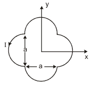
- 8A loop carrying current $I$ lies in the $x$-y plane as shown in the figure. the unit vector $\hat{ k }$ is coming out of the plane of the paper. the magnetic moment of the current loop is :View Solution
- 9An electron moving with a velocity ${\vec V_1} = 2\,\hat i\,\, m/s$ at a point in a magnetic field experiences a force ${\vec F_1} = - 2\hat j\,N$ . If the electron is moving with a velocity ${\vec V_2} = 2\,\hat j \,\,m/s$ at the same point, it experiences a force ${\vec F_2} = + 2\,\hat i\,N$ . The force the electron would experience if it were moving with a velocity ${\vec V_3} = 2\hat k$ $m/s$ at the same point isView Solution
- 10A square loop of area $25\,cm ^2$ has a resistance of $10\,\Omega$. The loop is placed in uniform magnetic field of magnitude $40.0 T$. The plane of loop is perpendicular to the magnetic field. The work done in pulling the loop out of the magnetic field slowly and uniformly in $1.0 sec$, will be $..........\times 10^{-3}$View Solution