Draw the effective equivalent circuit of the circuit shown in Fig, at very high frequencies and find the effective impedance. 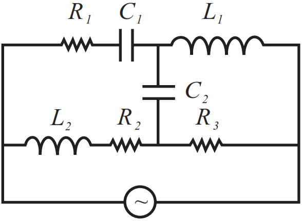
Download our app for free and get started
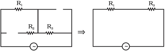
At high frequencies, capacitor ≈ short circuit (low reactance) and inductor ≈ open circuit (high reactance). Therefore, the equivalent circuit $Z ≈ R_1 + R_3$ as shown in the figure given below

Download our appand get started for free
Experience the future of education. Simply download our apps or reach out to us for more information. Let's shape the future of learning together!No signup needed.*
Similar Questions
- 1When an inductor L and a resistor R in series are connected across a 12 V, 50 Hz supply, a current of 0.5 A flows in the circuit. The current differs in phase from applied voltage by $\pi/3$ radian. Calculate the value of R.View Solution
- 2View SolutionDraw a schematic arrangement for winding of primary and secondary coils in a transformer with the two coils on separate limbs of the core. State its underlying principle and find the relation between the primary and secondary voltages in terms of the number of turns of the primary and secondary windings. How are the currents in the primary and secondary coils related to the voltages in the case of an ideal transformer?
- 3View SolutionExplain why the reactance provided by a capacitor to an alternating current decreases with increasing frequency.
- 4View SolutionObtain the resonant frequency and Q-factor of a series LCR circuit with L = 3.0H, C = 27μF, and R = 7.4Ω. It is desired to improve the sharpness of the resonance of the circuit by reducing its ‘full width at half maximum’ by a factor of 2. Suggest a suitable way.
- 5View Solution
- Distinguish between a conductor and a semi conductor on the basis of energy band diagram.
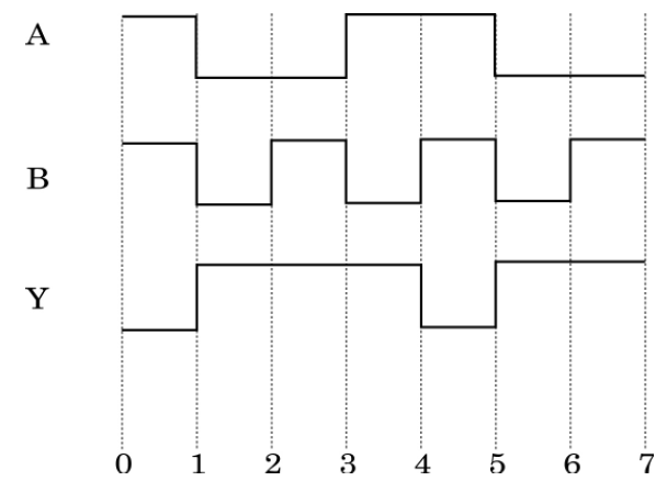
- The following figure shows the input waveforms (A, B) and the output waveform (Y) of a gate. Identify the gate, write its truth table and draw its logic symbol.
- 6The voltage and current in a series AC circuit are given by, $\text{V}=\text{V}_0\cos\omega\text{t}$ and $\text{i}=\text{i}_0\sin\omega\text{t}.$ What is the power dissipated in the circuit?View Solution
- 7View SolutionWrite two important considerations used while fabricating a Zener diode. Explain, with the help of a circuit diagram, the principle and working of a Zener diode as voltage regulator.
- 8View SolutionA series LCR circuit is connected to an ac source. Using the phasor diagram, derive the expression for the impedance of the circuit. Plot a graph to show the variation of current with frequency of the source, explaining the nature of its variation.
- 9View SolutionFind the time required for a 50Hz alternating current to change its value from zero to the rms value.
- 10View SolutionAn inductor 200 mH, capacitor 500 µF, resistor 10Ω are connected in series with a100 V, variable frequency a.c. source. Calculate the
- Frequency at which the power factor of the circuit is unity.
- Current amplitude at this frequency.
- Q-factor.