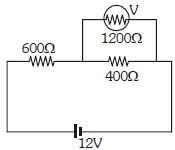
Find the error in reading of voltmeter ................ $\%$
Medium


Download our appand get started for free
Experience the future of education. Simply download our apps or reach out to us for more information. Let's shape the future of learning together!No signup needed.*
Similar Questions
- 1View SolutionThe potentiometer is best for measuring voltage, as
- 2$A$ wire of cross-section area $A$, length $L_1$, resistivity $\rho_1$ and temperature coefficient of resistivity $\alpha_1$ is connected to a second wire of length $L_2$, resistivity $\rho_2$ , temperature coefficient of resistivity $\alpha_1$ and the same area $A$, so that wire carries same current. Total resistance $R$ is independent of temperature for small temperature change if (Thermal expansion effect is negligible)View Solution
- 3Masses of three wires of copper are in the ratio of $1 : 3 : 5$ and their lengths are in the ratio of $5:3:1.$ The ratio of their electrical resistances areView Solution
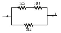
- 4Power dissipated across the $8\,\Omega $ resistor in the circuit shown here is $2\, watt$. The power dissipated in watt units across the $3\,\Omega $ resistor isView Solution
- 5What length of the wire of specific resistance $48 \times {10^{ - 8}}\,\Omega \,\,m$ is needed to make a resistance of $4.2 \, \Omega$ .............. $m$ (diameter of wire = $0.4\, mm$)View Solution
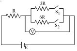
- 6In the circuit shown in figure reading of voltmeter is $V_1$ when only $S_1$ is closed, reading of voltmeter is $V_2$ when only $S_2$ is closed. The reading of voltmeter is $V_3$ when both $S_1$ and $S_2$ are closed thenView Solution
- 7When the power delivered by a $100\,volt$ battery is $40\,watts$ the equivalent resistance of the circuit is ........... $ohms$View Solution
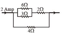
- 8In the adjoining circuit, the potential difference across $3\,\,\Omega $ is ................ $\mathrm{V}$View Solution
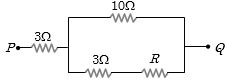
- 9In the circuit shown here, what is the value of the unknown resistor $R$ so that the total resistance of the circuit between points $P$ and $Q$ is also equal to $R$View Solution
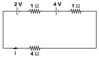
- 10For the circuit shown in the figure, the current $I$ will be .......$A$View Solution