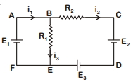
For the circuit given below, the Kirchoff's loop rule for the loop $BCDEB$ is given by the equation
NEET 2020, Medium


Download our appand get started for free
Experience the future of education. Simply download our apps or reach out to us for more information. Let's shape the future of learning together!No signup needed.*
Similar Questions
- 1A potentiometer has uniform potential gradient. The specific resistance of the material of the potentiometer wire is $10^{-7} \, ohm-meter$ and the current passing through it is $0.1\, ampere$; cross-section of the wire is $10^{-6}\, m^2$. The potential gradient along the potentiometer wire isView Solution
- 2Assertion $(A):$ In a meter bridge experiment, null point for an unknown resistance is put inside an enclosure maintained at a higher temperature. The null point can be obtained at the same $p$ as before by decreasing the value of the standard resistance.View Solution
Reason $(R):$ Resistance of metal increases with increase in temperature.
- 3A current $I$ is passing through a wire having two sections $P$ and $Q$ of uniform diameters $d$ and $d/2$ respectively. If the mean drift velocity of electrons in sections $P$ and $Q$ is denoted by $v_P$ and $v_Q$ respectively, thenView Solution
- 4$AB$ is a wire of uniform resistance. The galvanometer $G$ shows no current when the length $AC = 20\,cm$ and $CB = 80\, cm$. The resistance $R$ is equal to .............. $\Omega $View Solution
- 5A steady current $i$ is flowing through a conductor of uniform cross-section. Any segment of the conductor hasView Solution
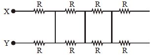
- 6Net resistance between $X$ and $Y$ isView Solution
- 7Incandescent bulbs are designed by keeping in mind that the resistance of their filament increases with the increase in temperature. If at room temperature, $100 \mathrm{~W}, 60 \mathrm{~W}$ and $40 \mathrm{~W}$ bulbs have filament resistances $\mathrm{R}_{100}, \mathrm{R}_{60}$ and $\mathrm{R}_{40}$, respectively, the relation between these resistances isView Solution
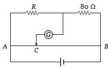
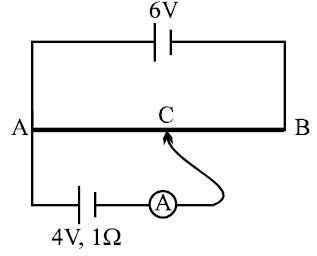
- 8$A \,6 \,V$ battery of negligible internal resistance is connected across a uniform wire of length $1\, m$. The positive terminal of another battery of emf $4\,V$ and internal resistance $1\, \Omega$ is joined to the point $A$ as shown in figure. The ammeter shows zero deflection when the jockey touches the wire at the point $C$. The $AC$ is equal toView Solution
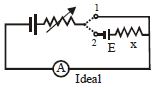
- 9In the circuit shown the variable resistance is so adjusted that the ammeter reading is same in both the position $1$ and $2$ of the key. The reading of ammeter is $2A$. If $E = 20V$, then $x$ is :- ................... $\Omega$View Solution
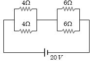
- 10Four resistances are connected in a circuit in the given figure. The electric current flowing through $4\, ohm$ and $6\, ohm$ resistance is respectivelyView Solution