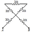
For the circuit shown in the figure , the equivalent resistance between $A$ and $B$ is ............. $\Omega$
Medium
Download our app for free and get started
When a battery is connected between $\mathrm{A}$ and $\mathrm{B}.$ no current will pass through the upper triangle and the equivalent resistance between $\mathrm{A}$ and $\mathrm{B}$ is $4\, \Omega.$

Download our appand get started for free
Experience the future of education. Simply download our apps or reach out to us for more information. Let's shape the future of learning together!No signup needed.*
Similar Questions
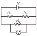
- 1In the circuit shown, $R_1$ is increased. What happens to the reading of the voltmeter (ideal)?View Solution
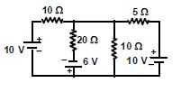
- 2The value of current through the $20\,\Omega $ resistor is ............ $amp$View Solution
- 3Two resistances equal at $0\,^oC$ with temperature coefficient of resistance $\alpha _1$ and $\alpha _2$ joined in series act as a single resistance in a circuit. The temperature coefficient of their single resistance will beView Solution
- 4Consider the circuit shown below where all resistors are $1 \,k \Omega$. If a current of magnitude $1 \,mA$ flows through the resistor marked $X$, the potential difference measured between points $P$ and $Q$ are ..............$V$View Solution
- 5View SolutionAssertion : Ohm's law is applicable for all conducting elements.
Reason : Ohm's law is a fundamental law
- 6Two electric bulbs whose resistances are in the ratio of $1 : 2$ are connected in series. The powers dissipated in them have the ratioView Solution
- 7A uniform heating wire of resistance $36\, \Omega$ is connected across a potential difference of $240\, {V}$ The wire is then cut into half and potential difference of $240\, {V}$ is applied across each half separately. The ratio of power dissipation in first case to the total power dissipation in the second case would be $1: {x}$, where ${x}$ is........... .View Solution
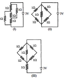
- 8The figure shows three circuits $I, II$ and $III$ which are connected to a $3\,V$ battery. If the powers dissipated by the configurations $I, II$ and $III$ are $P_1 , P_2$ and $P_3$ respectively, thenView Solution
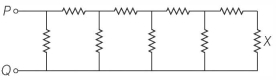
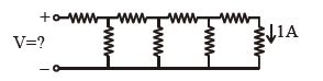
- 9Each element in the finite chain of resistors shown in the figure is $\,1\,\Omega $ . A current of $1\, A$ flows through the final element. Then what is the potential difference $V$ across input terminals of the chain .................. $\mathrm{volt}$View Solution
- 10View SolutionThe length of the wire is doubled. Its conductance will be